Surge arrester with a cage design

a cage design and arrester technology, applied in the direction of overvoltage protection resistors, emergency protective arrangements for limiting excess voltage/current, mechanical devices, etc., can solve the problems of complex and expensive, easy to tear, and the risk of the reinforcing elements being weakened in the hole area in such a way that they tear, etc., to achieve the effect of easy manufactur

Inactive Publication Date: 2013-05-21
TRIDELTA UBERSPANNUNGSABLEITER
View PDF19 Cites 11 Cited by
  • Summary
  • Abstract
  • Description
  • Claims
  • Application Information

AI Technical Summary

Benefits of technology

[0014]The object of the invention is thus to provide a surge arrester of this generic type with a cage design, which can be manufactured easily and ensures that the reinforcing elements are securely anchored in the end fittings.

Problems solved by technology

One problem with surge arresters such as these is to attach the reinforcing elements securely to the end fittings such that the necessary strength is maintained even in the event of mechanical loads such as those, which occur in the case of surge arresters installed in the open air.
Although this allows a surge arrester to be designed in an effective manner, this results in the problem of the thread cutting into the GFC rods that are used as reinforcing elements, without damaging them.
This is complex and expensive.
Although it is considerably simpler to form a hole in the direction at right angles to the extension direction of the GFC rods which are used as reinforcing elements than to cut a thread in them, this configuration results in the risk of the reinforcing elements being weakened in the area of the hole in such a way that they tear.
In the case of all the abovementioned documents, in which the reinforcing elements are held with a friction lock or force fit in the end fitting, it is difficult to apply the necessary tensile strength.
It is difficult to manufacture surge arresters with a crimp sleeve since the crimp sleeve must be applied while the reinforcing element is being held under tension.
The crimping process can also result in the rod being damaged without this being evident.
In the case of those surge arresters in which the reinforcing elements are held in the end fitting by means of screws, this necessitates considerable weakening of the reinforcing element in the area of the screw.

Method used


Image

  • Surge arrester with a cage design
  • Surge arrester with a cage design
  • Surge arrester with a cage design

Examples


Embodiment Construction

[0023]While the present invention is susceptible of embodiment in various forms, there is shown in the drawings and will hereinafter be described a presently preferred embodiment with the understanding that the present disclosure is to be considered an exemplification of the invention and is not intended to limit the invention to the specific embodiment illustrated. It should further be understood that the title of this section of this specification, namely, “Detailed Description of the Invention,” relates to a requirement of the United States Patent Office and does not imply, nor should be inferred to limit the subject matter disclosed herein.

[0024]In the present disclosure, the words “a” or “an” are to be taken to include both the singular and the plural. Conversely, any reference to plural items, shall, where appropriate, include the singular.

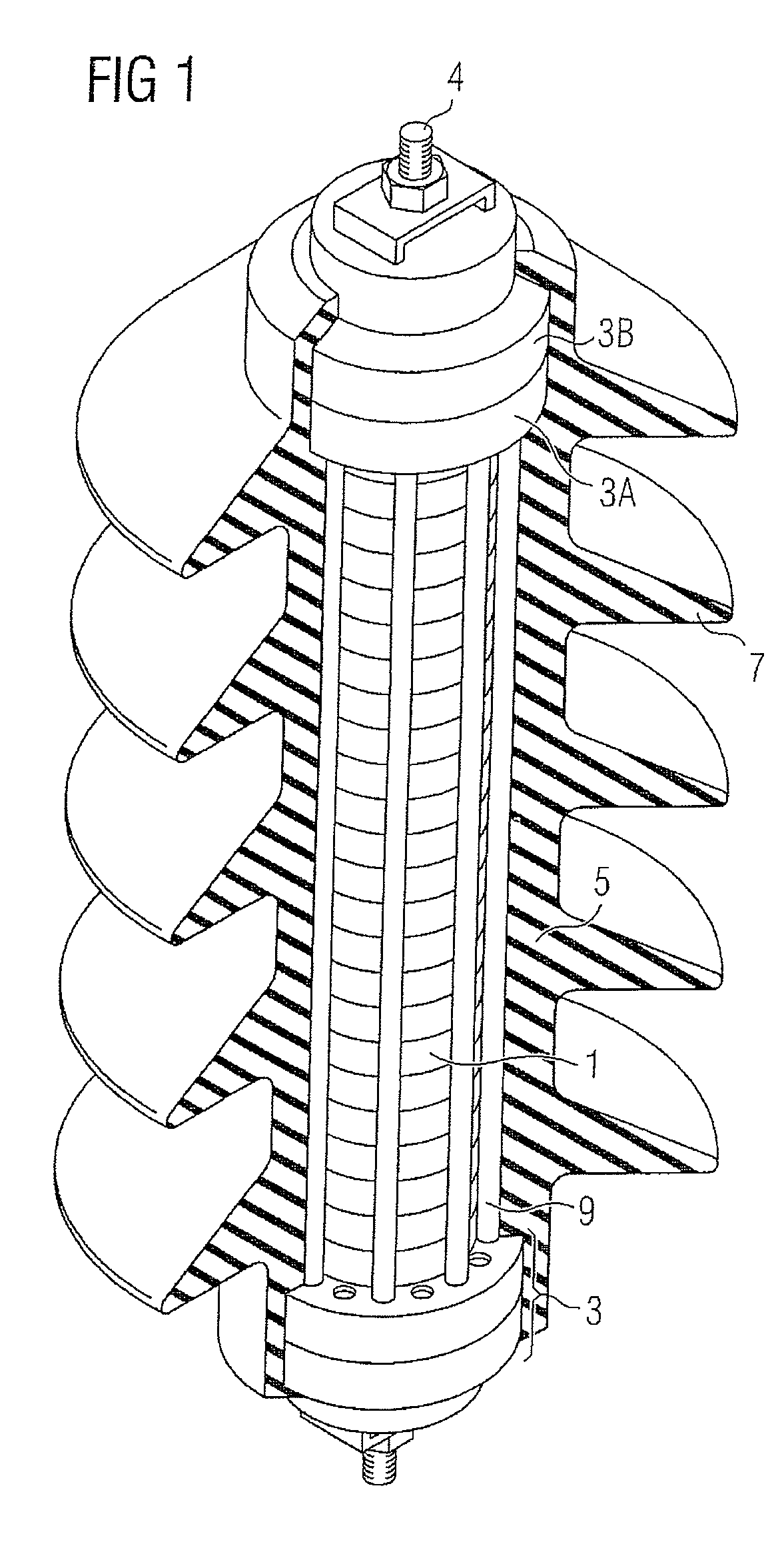
[0025]The surge arrester with a cage design as shown in FIG. 1 contains at least one varistor block 1. Known ceramic wafers with a voltage-...


PUM


Abstract

The invention relates to a surge arrester having at least one varistor block 1, one end fitting 3, one reinforcing element 9 which holds the varistor block 1 firmly on the end fitting 3 with a tensile load, and at least one anchoring element 27 which holds the reinforcing element 9 firmly on the end fitting 3 with a tensile load wherein the anchoring element 27 has at least one edge 29 which cuts into the reinforcing element 9. The anchoring element 27 is preferably a cutting-ring screw union.

Description

CROSS-REFERENCE TO RELATED APPLICATIONS[0001]The present application is a Continuation of International Application No. PCT / EP2006 / 062433, filed May 18, 2006, which claims the benefit of German Application No. DE 102005024206.5, filed May 25, 2006. All of the above listed applications are hereby incorporated by reference herein in their entireties.BACKGROUND OF THE INVENTION[0002]The invention relates to a surge arrester having a cage design, as is known by way of example from JP 62-149511 (application number). Surge arresters are connected between live cables and earth in electrical power supply systems in order, when an overvoltage occurs on the line, to dissipate this overvoltage to earth and thus to protect other components in the power supply network. A surge arrester such as this contains a stack of varistor blocks, which is held between two connecting elements. This arrangement is accommodated in a housing.[0003]In order to ensure that the varistor blocks make good contact wi...

Claims


Application Information

Patent Timeline
Patent Type & Authority Patents(United States)
IPC IPC(8): H02H3/22H02H9/06
CPCH01C7/12H01C7/10
Inventor KLAUBE, HARTMUTLAURITSCH, HUBERT
Owner TRIDELTA UBERSPANNUNGSABLEITER
Why Eureka
Try Eureka