Ultra broadband capacitor
a technology of broadband capacitors and capacitors, applied in the direction of variable capacitors, fixed capacitors, fixed capacitor details, etc., can solve the problems of not having a design generally encompassing all of the desired characteristics, a relatively complex and expensive production technique for mruz's wideband capacitors, etc., to achieve the effect of reducing the number of processing steps, increasing the number of secondary capacitive elements, and being more efficient and less expensiv
- Summary
- Abstract
- Description
- Claims
- Application Information
AI Technical Summary
Benefits of technology
Problems solved by technology
Method used
Image
Examples
first embodiment
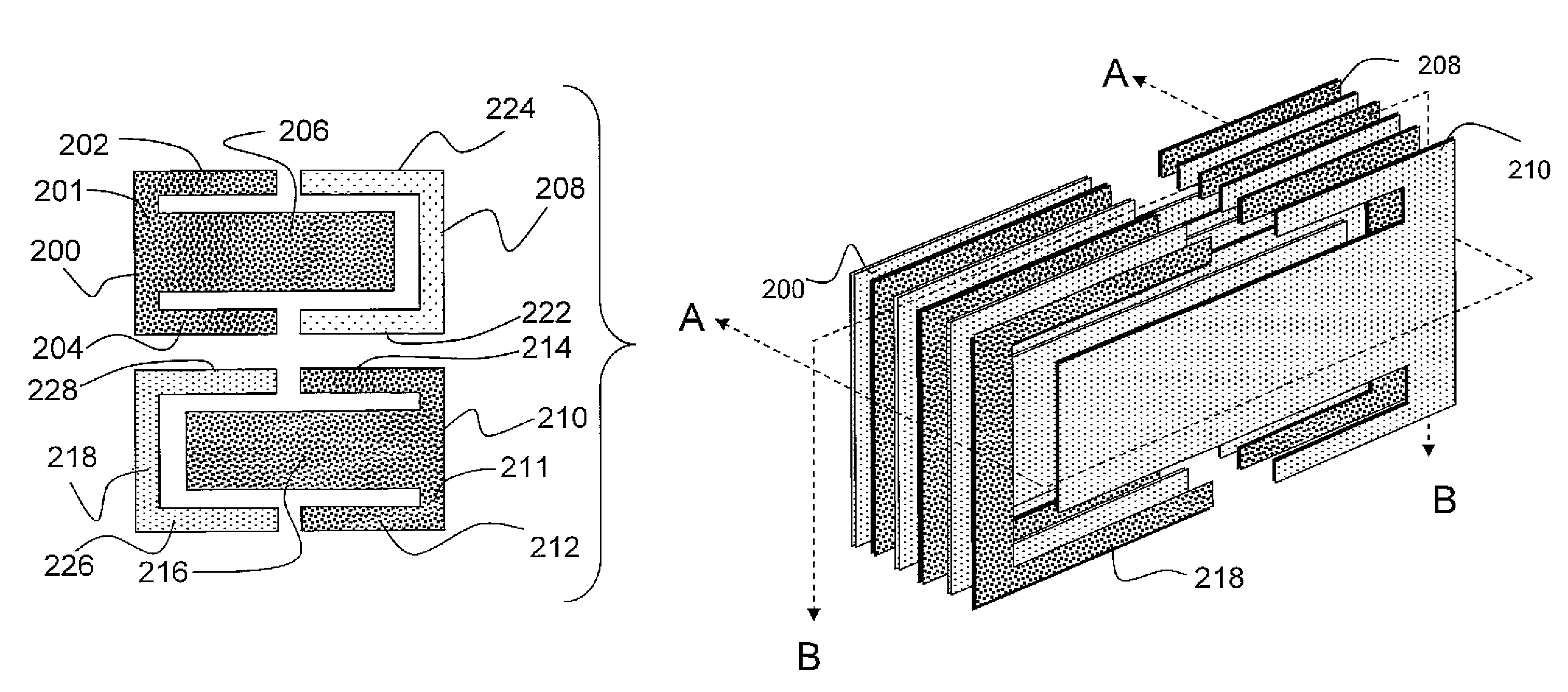
[0046]Reference will now be made in detail to the presently preferred embodiments of the subject ultra broadband capacitors. Referring now to the drawings, FIGS. 2A-2G illustrate the structure of a capacitor constructed in accordance with the present subject matter that has provided therein significant amounts of reproducible secondary and tertiary capacitive elements. FIG. 2A illustrates a planar view of a unit cell, or pair of electrodes that are replicated many times in a stack of electrodes as may be employed to produce a broadband (i.e., wideband) capacitor in accordance with present technology. In an exemplary construction, over a hundred sets of electrode pairs may be provided in any one capacitor. Those of ordinary skill in the art, however, will appreciate that the exact number of cells provided depends on many variables including, for example, the target design value for the capacitor. The number of unit cells and corresponding electrodes illustrated in the drawings and di...
second embodiment
[0063]FIGS. 4A-4C illustrate the present subject matter including an alternative methodology for increasing secondary capacitive regions within the overall multilayer capacitor structure. As illustrated in FIG. 4A, electrode pairs now consist of mirror image designs that intersect with multiple long linear relations. Electrodes 300, 310 are provided in a single plane with triple extension arms corresponding to central portions 300′ and 310 respectively, along with side arms 302, 304 and 312, 314. The second layer 324-327 is again a mirror image of the 300-310 pair; pairs of such first and second electrode sheets of FIG. 4A will be stacked together with alternating dielectric layers (not shown) to form overlapping relationships with each other as seen in the perspective view of FIG. 4B. The overlap between opposing polarity electrodes in adjacent sheets of a unit cell will form the primary capacitance described above with respect to FIGS. 2A-2D.
[0064]Referring still to FIGS. 4A-4C, e...
third embodiment
[0066]In accordance with the present subject matter, another way of incorporating parallel capacitance in the structure is by incorporating added layers in the stack. In the embodiment of FIGS. 5A and 5B, the same structure introduced in FIGS. 2A-2G is provided with additional electrodes 411, 413 and 411′, 413′ above and below the stack of electrode sets 401-403 and 405-407. In one embodiment, electrodes 411, 413, 411′ and 413′ may be generally rectangular in shape. Again, those of ordinary skill in the art will appreciate that the stack of electrodes 401-403 and 405-407 sets may correspond to many more electrodes than illustrated, for example on the order of about one hundred layers or more. The electrodes, 411, 413 along with their counterpart at the other end, 411′, 413 provide another stacking area capacitance, as can be seen in the perspective of FIG. 5B. For ease of illustration, the “C” shaped electrodes 403 and 405 have been omitted from the perspective view of FIG. 5B, and ...
PUM
| Property | Measurement | Unit |
|---|---|---|
| distance | aaaaa | aaaaa |
| distance | aaaaa | aaaaa |
| capacitance | aaaaa | aaaaa |
Abstract
Description
Claims
Application Information
 - R&D
- Intellectual Property
- Life Sciences
- Materials
- Tech Scout
- Unparalleled Data Quality
- Higher Quality Content
- 60% Fewer Hallucinations
Browse by: Latest US Patents, China's latest patents, Technical Efficacy Thesaurus, Application Domain, Technology Topic, Popular Technical Reports.
© 2025 PatSnap. All rights reserved.Legal|Privacy policy|Modern Slavery Act Transparency Statement|Sitemap|About US| Contact US: help@patsnap.com


