Micro-architected materials for heat sink applications

a heat sink and micro-architecture technology, applied in the field of heat sinks, can solve the problems of poor heat transfer performance of louvered fins, difficulty in cooling odd shaped surfaces or even substantially non-planar surfaces, and difficulty in supporting mechanical loads, etc., to achieve the effect of increasing the surface area to volume ratio

Inactive Publication Date: 2013-06-04
HRL LAB
View PDF17 Cites 42 Cited by
  • Summary
  • Abstract
  • Description
  • Claims
  • Application Information

AI Technical Summary

Problems solved by technology

Certain forms of heat sinks use fins or louvers but these heat sinks have difficulty supporting mechanical loads.
In addition, odd shaped surfaces or even substantially non planar surfaces can be difficult to cool with heat sinks known in the art.
These designs (with the exception of louvered fins) may have worse performance in terms of low heat transfer than truss designs.
Furthermore, louvered fin designs cannot support loads, unlike truss designs, and are expensive to manufacture.
The use of a truss architecture for active cooling has been reported in literature (for instance, Lu, Valdevit, Evans, “Active cooling by metallic sandwich structures with periodic cores”, Progress in Materials Science 50 (2005) 789-815) However, the only fabrication methods described are expensive, limited to a single truss layer, and limited to large truss unit cell sizes.
The structures described therein are constrained to simple, flat geometries, do not have enhancements for increased convective heat transport, and are not designed to support a load while transferring heat.

Method used


Image

  • Micro-architected materials for heat sink applications
  • Micro-architected materials for heat sink applications
  • Micro-architected materials for heat sink applications

Examples


Embodiment Construction

[0024]In the following detailed description, only certain exemplary embodiments of the present invention are shown and described, by way of illustration. As those skilled in the art would recognize, the described exemplary embodiments may be modified in various ways, all without departing from the spirit or scope of the present invention. Accordingly, the drawings and description are to be regarded as illustrative in nature, and not restrictive.

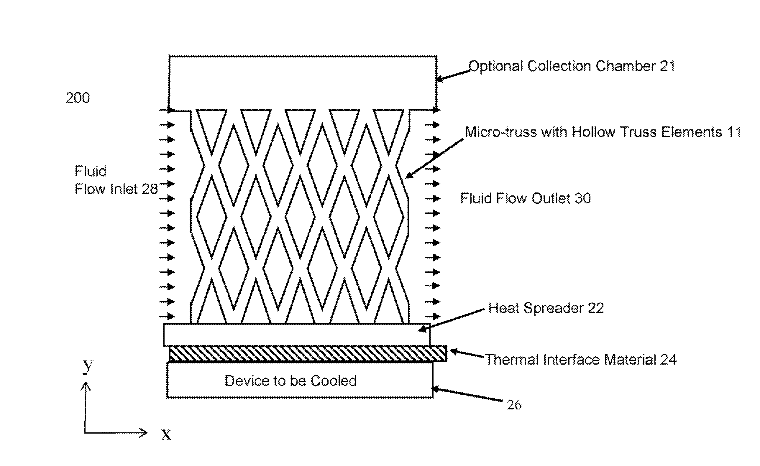
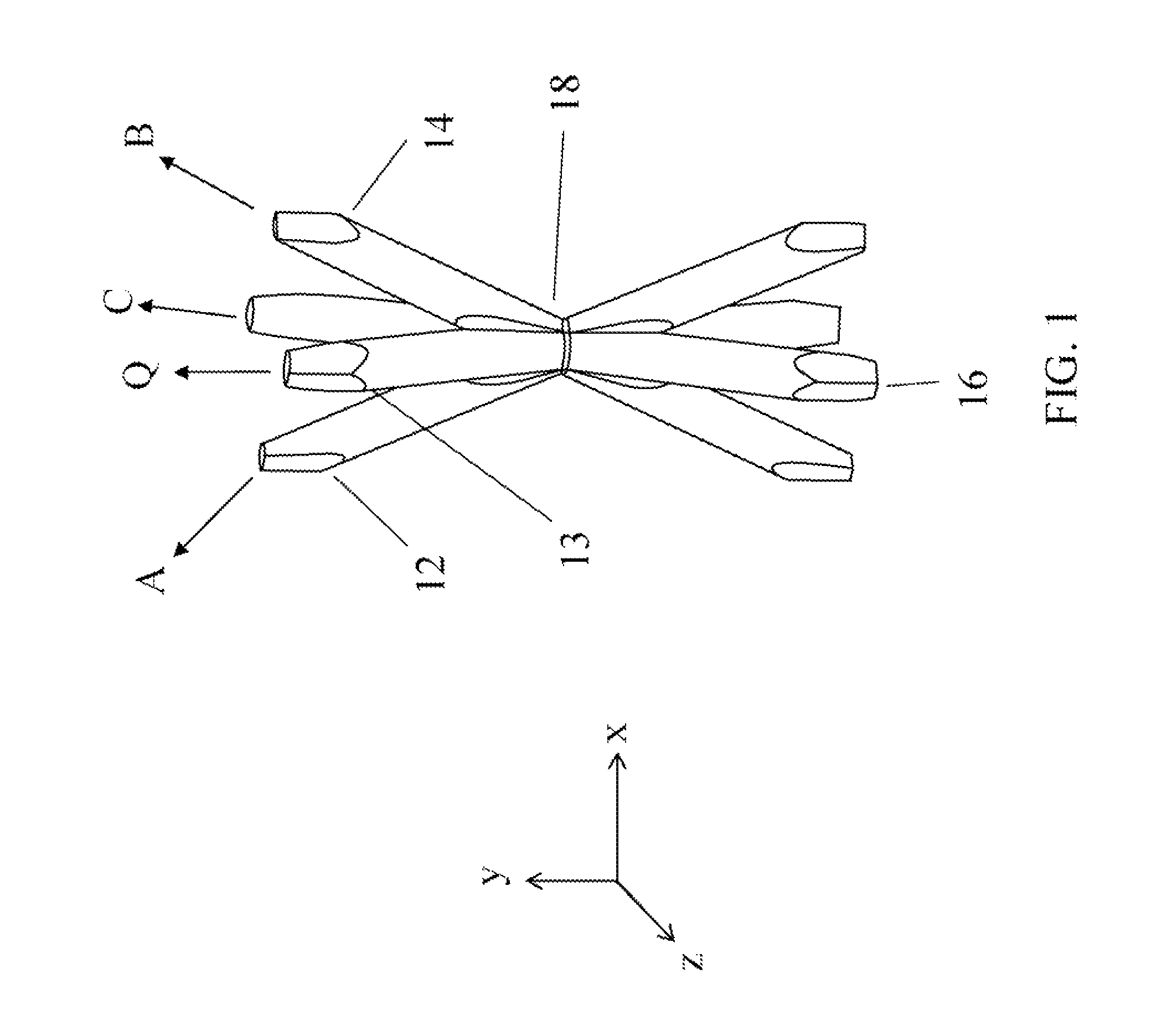
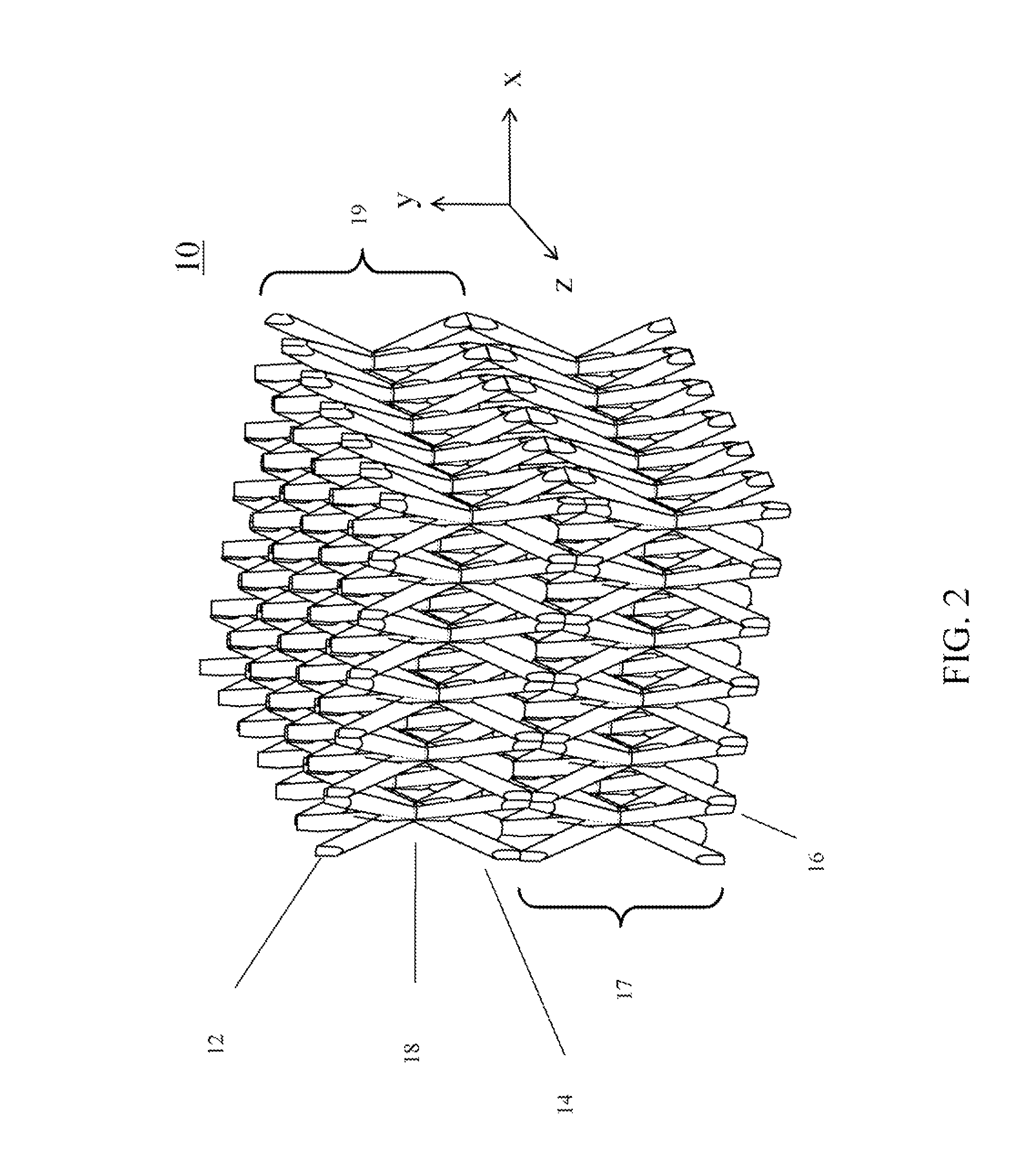
[0025]In the context of embodiments of the present invention, a three-dimensional ordered microstructure is referred to as an ordered three-dimensional structure at the micrometer scale. In one embodiment of the present invention, a heat sink composed of a three-dimensional ordered microstructure is provided. Here, the heat sink transfers heat from a device to be cooled to the environment through conduction and / or convection. Optionally, the three-dimensional ordered microstructure may be attached to a heat spreader.

[0026]An alternative embod...


PUM

PropertyMeasurementUnit
angleaaaaaaaaaa
sizeaaaaaaaaaa
sizeaaaaaaaaaa

Abstract

A heat sink comprising a heat spreader attached to a three-dimensional ordered open-cellular microstructure material. The three-dimensional ordered open-cellular microstructure material has dimensions that allow for large surface area to volume ratios. The three-dimensional ordered open-cellular microstructure may be comprised of hollow truss elements and partially filled with a thermally conductive material or a fluid.

Description

FIELD OF THE INVENTION[0001]The present invention relates to the area of heat sinks using conduction and or convection, and in particular, heat sinks capable of supporting mechanical loads.BACKGROUND OF THE INVENTION[0002]Heat sinks transfer heat from a hot area to a cooler area. Certain forms of heat sinks use fins or louvers but these heat sinks have difficulty supporting mechanical loads. In addition, odd shaped surfaces or even substantially non planar surfaces can be difficult to cool with heat sinks known in the art. Various heat sink designs include fins, pin fins, corrugated, and louvered fins. These designs may be incorporated in heat pipes and heat spreaders. These designs (with the exception of louvered fins) may have worse performance in terms of low heat transfer than truss designs. Furthermore, louvered fin designs cannot support loads, unlike truss designs, and are expensive to manufacture.[0003]The use of a truss architecture for active cooling has been reported in l...

Claims


Application Information

Patent Timeline
Patent Type & Authority Patents(United States)
IPC IPC(8): F28F7/02
CPCF28F7/02F28F13/003F28F21/06F28D2021/0029H01L23/3733H01L23/427H01L23/473H01L2924/0002H01L2924/00
Inventor ROPER, CHRISTOPHER S.CARTER, WILLIAM B.
Owner HRL LAB
Why Eureka
Try Eureka