
Surfactant incorporated nanostructure for pressure drop reduction in oil and gas lines

a technology of nanostructure and oil and gas lines, applied in the direction of transportation and packaging, oxygen/ozone/oxide/hydroxide, other chemical processes, etc., can solve the problems of increasing production costs, reducing the production efficiency of the fluid transport pipe, and generating substantial pressure drops. , to achieve the effect of reducing the pressure drop generated

Inactive Publication Date: 2009-05-21
UNIV OF CENT FLORIDA RES FOUND INC +1
View PDF16 Cites 3 Cited by
  • Summary
  • Abstract
  • Description
  • Claims
  • Application Information

AI Technical Summary

Benefits of technology

The present invention provides a method and composition for reducing pressure drops in fluid flow through pipelines. The method involves spraying a mixture of nano-sized cerium oxide particles and a surfactant onto the fluid stream in the pipeline. The cerium oxide particles are suspended in a non-polar hydrocarbon solvent, such as toluene, and the surfactant helps to reduce friction at the pipe wall and gas / liquid interface. The cerium oxide particles are also incorporated into a ceria nanoparticle mixture with organic surfactants, which helps to reduce wall friction and interfacial friction. The ceria nanoparticle mixture can be sprayed onto the fluid stream in a pipeline to decrease pressure drop. The invention also includes a method for preparing a suspension of cerium oxide nanoparticles in non-polar hydrocarbon solvent with a surfactant. The composition of matter includes a suspension of cerium oxide nanoparticles in non-polar hydrocarbon solvent with a surfactant. The technical effects of the invention include reducing pressure drops in fluid flow through pipelines, improving fluid flow control, and reducing the amount of nanoparticles needed for treatment.

Problems solved by technology

It is well known that friction or “drag” between the fluids and the pipe or vessel wall causes substantial pressure drops as the fluids move along each wall.
At the pipe wall, the roughness is caused by microscopic and / or larger pits, scratches, and other imperfections in the pipe wall which result during the manufacture of the pipe or from corrosion, abrasion, and the like during use.
The pressure drop generated as fluid flows through a pipe is an unwelcome culprit that creates bottlenecks, interferes with fluid flow and increases production costs substantially.
The Charron arrangement would substantially increase the cost and manufacture of the pipe used to convey fluids.
The drawback of this system is that the porous lining and injected lubricant must be adjusted to receive hydrophilic or oleophilic fluids.
U.S. Pat. No. 5,220,938 to Kley uses a friction reducing material, which includes polymeric material, liners and liners with riblets to reduce pressure drops generated by fluid flow; such materials can be an expensive addition to a pipeline.
None of the prior art references use surfactant incorporated nano particles to reduce pressure drop and thereby increase or improve the flow rate of fluids in a pipeline.

Method used


Image

  • Surfactant incorporated nanostructure for pressure drop reduction in oil and gas lines
  • Surfactant incorporated nanostructure for pressure drop reduction in oil and gas lines
  • Surfactant incorporated nanostructure for pressure drop reduction in oil and gas lines

Examples


example

Preparation of Nano Ceria Mixture

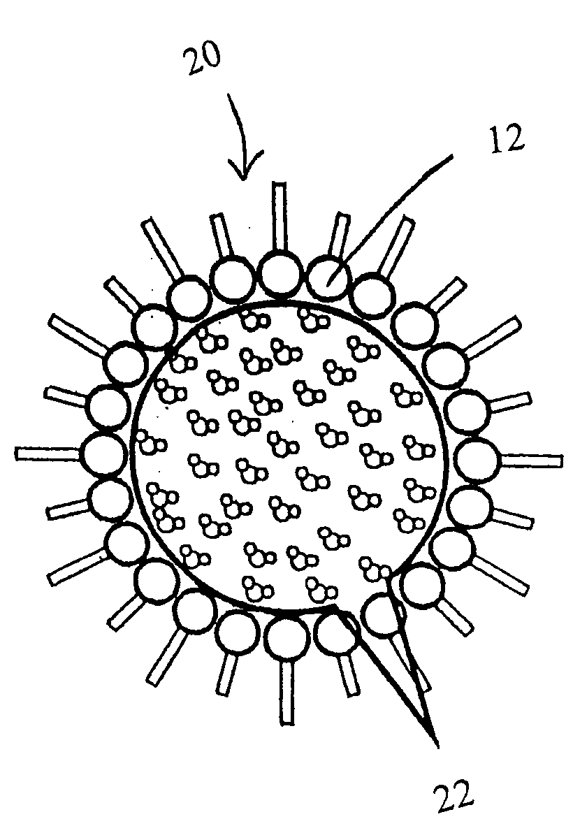
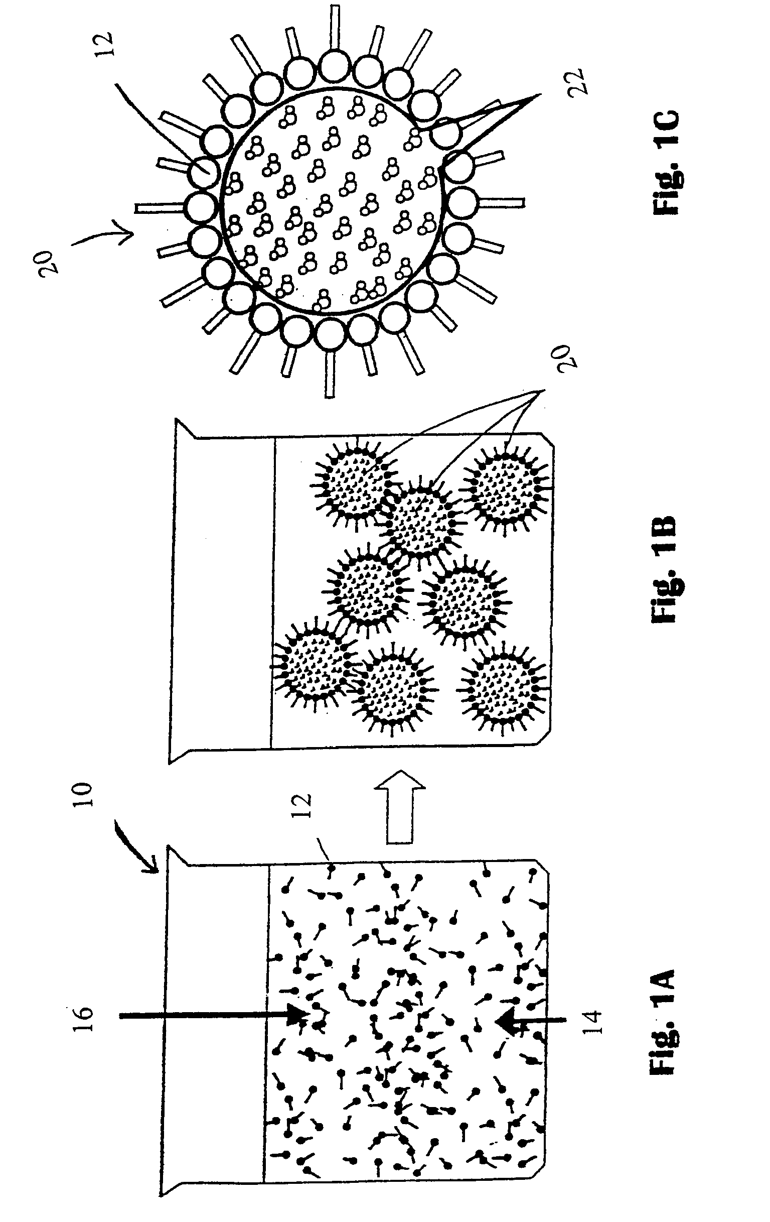
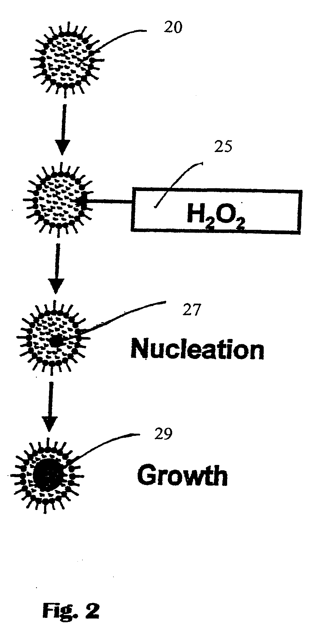
[0039]Cerium oxide nanoparticles of a size approximately 2 nm to approximately 10 nm in diameter, are prepared by a process including the steps of dissolving approximately 0.5 grams to approximately 1.0 grams of Ce(NO3)3.6H2O in deionized water to make approximately 10 mls of solution to form a first solution, followed by dissolving approximately 3 grams to approximately 4 grams of AOT (surfactant) in approximately 200 ml of solvent to form a second solution, followed by combining the first and the second solutions, followed by stirring the combined solutions for approximately 30 minutes, and drop wise adding approximately 30% hydrogen peroxide (H2O2) until the stirred combined solution becomes yellow, and subsequently stirring for approximately 30 minutes to approximately 60 minutes more.

[0040]Thus, aqueous reverse micelles (RMs) form surfactant aggregates in nonpolar solvents that enclose packets of aqueous solution in their interior. The size of t...


PUM

PropertyMeasurementUnit
diameteraaaaaaaaaa
diameteraaaaaaaaaa
diameteraaaaaaaaaa

Abstract

Nano-sized rare earth metal oxide particles are prepared from aqueous reverse micelles. The engineered nanoparticles have large surface area to volume ratios, and uniformly incorporate a surfactant in each particle, so that when applied to the inner surface of a pipeline or sprayed onto a fluid stream in a pipeline, the particles reduce the roughness of the inside surface of pipe being used to transport fluid. The application of a nanolayer of this novel nanoceria mixture causes a significant reduction in pressure drops, friction, and better recovery and yield of fluid flowing through a pipeline.

Description

[0001]This invention claims priority based on U.S. Provisional Application Ser. No. 60 / 588,097 filed on Jul. 15, 2004 the contents of which are incorporated herein by reference.FIELD OF THE INVENTION[0002]This invention relates to the control of pressure drop in fluid flow technology and more particularly to a method and composition of matter for reducing friction or pressure drop in oil and gas pipelines and similar processing structures using surfactant incorporated functional nano particles.BACKGROUND AND PRIOR ART[0003]The chemical industry and the petroleum industry use pipes, commonly called “pipelines” or “oil and gas pipelines” for conveying gas, water, chemical reagents, petroleum effluents, and the like, over long distances. It is well known that friction or “drag” between the fluids and the pipe or vessel wall causes substantial pressure drops as the fluids move along each wall. The drag experienced by flowing fluids in a pipeline has been directly related to the “roughne...

Claims


Application Information

Patent Timeline
Patent Type & Authority Applications(United States)
IPC IPC(8): C09K3/00
CPCF17D1/16Y10T137/0391
Inventor SEAL, SUDIPTAJEPSON, WILLIAM P.DESHPANDE, SAMEERKUIRY, SURESH C.PATIL, SWANAND D.
Owner UNIV OF CENT FLORIDA RES FOUND INC
Learn More