
Spout cap having two steps type straw part

a straw part and spout cap technology, which is applied in the direction of liquid dispensing, liquid flow controllers, packaging, etc., can solve the problems of engine oil flow out, liquefied oil such as lubricant oil is occasionally flowed out in unintended places, and is difficult to re-seal the container

Inactive Publication Date: 2013-06-04
CONTINENTAL CAN CO INC
View PDF20 Cites 3 Cited by
  • Summary
  • Abstract
  • Description
  • Claims
  • Application Information

AI Technical Summary

Benefits of technology

The present invention is a spout cap with a two steps type straw part. The cap is designed to maintain its standard size and shape, and the straw parts are constructed in two steps to ensure that contents in the container can be correctly poured into the desired place. This invention helps to improve the user experience and facilitates the use of the spout cap.

Problems solved by technology

Also, in order to prevent any person from pouring impurities such as a poison into the liquefied article or from diluting the liquefied article for reducing the purity, it is necessary that once the container is open, it is impossible to re-seal the container.
However, although these can plugs are good for sealing, the liquefied oil such as lubricant oil is occasionally flowed out in unintended places when the oil is poured out of the metal container since the height of the can plug is low.
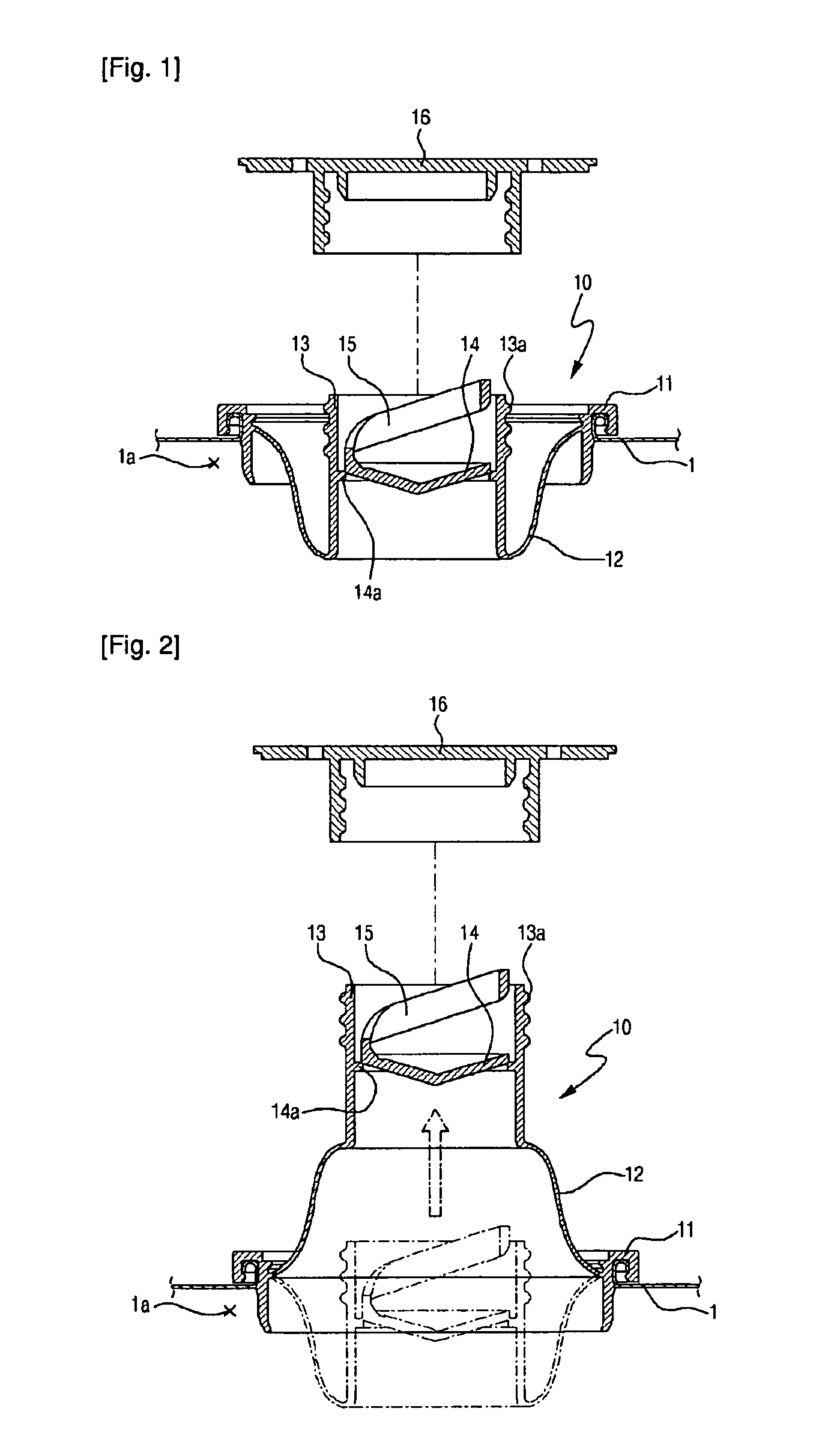
However, in this type of prior art spout cap (10), while the functions for preventing from contaminating and for sealing are good, there is a drawback that the engine oil may be flowed out since the length of the straw part (12) is so short not to be inserted into an engine oil hole, an oiling hole, and the like when the straw part (12) is drawn out of the can plug (16).
To solve this drawback, only extending the length of the straw part results in the reduction of the interior volume in the metal container, and it is limited to raise the height of the pouring outlet so that the prior automatic coupling cannot be used because the height of the assembled spout is raised.
However, in the mass production system, although the metal container and the can plug shall be coupled together by means of the automatic production line, it is difficult to combine the can plug with the metal container, since the can plug falls down or tips over due to the higher length of the can plug, and therefore the production process must be modified.

Method used


Image

  • Spout cap having two steps type straw part
  • Spout cap having two steps type straw part
  • Spout cap having two steps type straw part

Examples


Embodiment Construction

[0030]Hereinafter, the spout cap having a two steps type straw part according to one embodiment of the present invention will be described in detail, referring to the accompanying drawings.

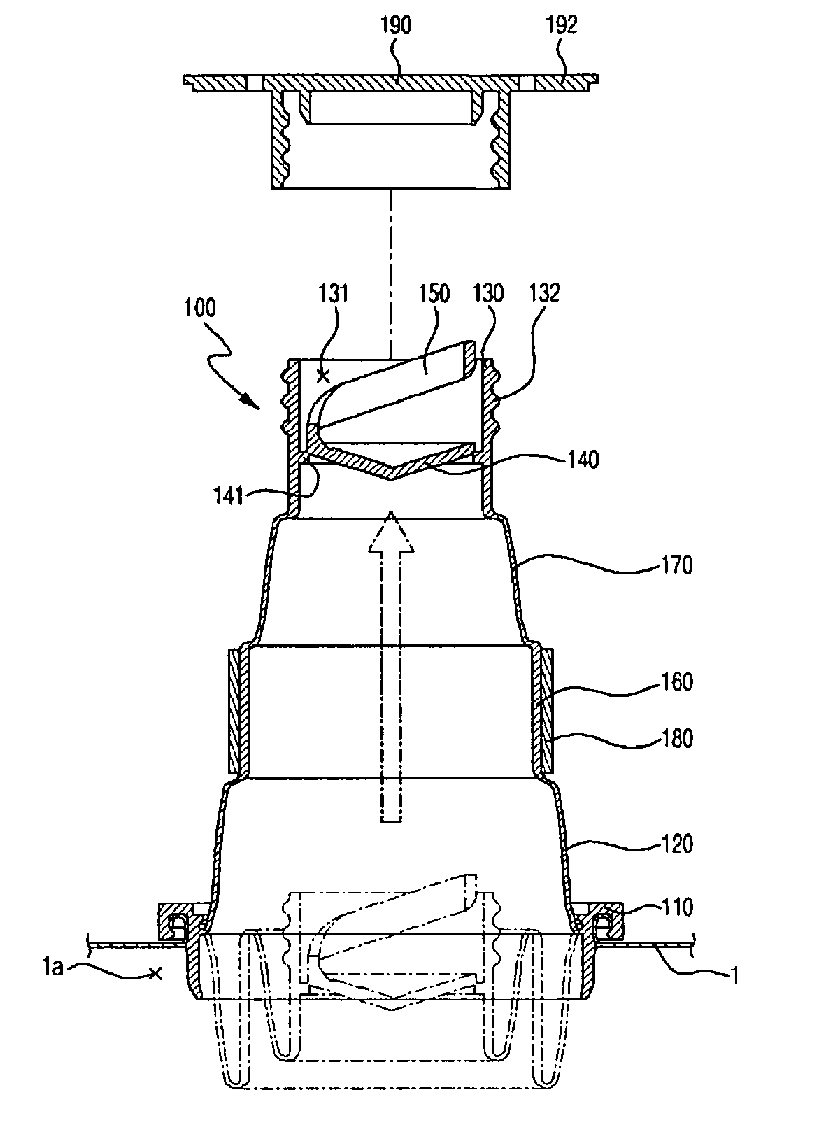
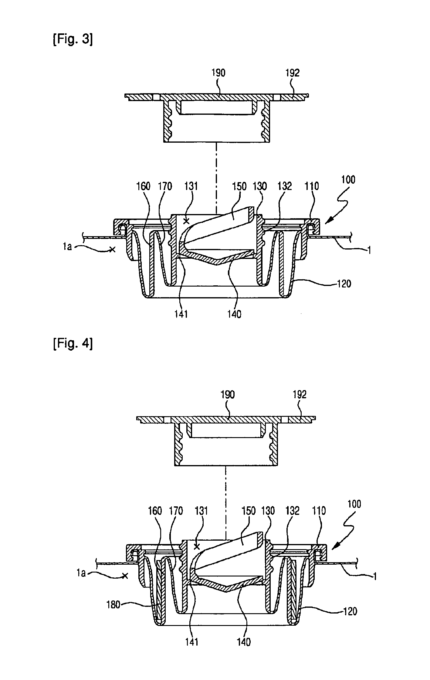
[0031]FIG. 3 is a cross-section showing the spout cap having a two steps type straw part according to one embodiment of this invention in which the two steps type straw part is in an overlapped state, FIG. 4 is a cross-section showing the spout cap having a two steps type straw part according to an alternative embodiment of this invention in which the two steps type straw part is in an overlapped state, FIG. 5 is a cross-section showing the two steps type straw part of FIG. 4 in a drawn out state, FIG. 6 is a cross-section showing the spout cap having a two steps type straw part according to the another embodiment of this invention in which the two steps type straw part is in an overlapped state, and FIG. 7 is a cross-section showing the spout cap having a two steps type straw part according to th...


PUM


Abstract

A spout cap having a two steps type straw part comprises a coupling part fixedly coupling with the pouring hole of the metal container; a first straw part extending at a predetermined length on the interior face of the coupling part; a cap coupling part having a pouring outlet through which contents in the metal container flow out, wherein the cap coupling part is selectively positioned in an overlapped disposition or an unfolded disposition with respect to the first straw part; an extension part between the first straw part and the cap coupling part, wherein the extension part is capable of extending the unfolded length when the cap coupling part is unfolded with respect to the first straw part; a second straw part extended from the upper inner face of the extension member at a predetermined length and coupled with the lower end of the cap coupling part.

Description

CROSS-REFERENCE TO RELATED APPLICATIONS[0001]This patent application is a U.S. National Phase application under 35 U.S.C. §371 of International Application No. PCT / KR2008 / 003164, filed on Jun. 5, 2008, entitled SPOUT CAP HAVING TWO STEPS TYPE STRAW PART, which claims priority to Korean patent application number 20-2008-0001486, filed Jan. 31, 2008 and Korean patent application number 10-2008-0034704, filed Apr. 15, 2008.TECHNICAL FIELD[0002]This invention relates to a spout cap having a two steps type straw part, and more specifically to a spout cap having a two steps type straw part which is designed to retain the outermost diameter and the entire assembly height of the spout cap as the same standard of the prior art, and the straw parts by which contents in the container are flowed out are constructed as a two steps type so that contents in the container can be correctly poured into the desired place.BACKGROUND ART[0003]The present invention relates to a spout cap, and specificall...

Claims


Application Information

Patent Timeline
Patent Type & Authority Patents(United States)
IPC IPC(8): B67D3/00
CPCB65D47/063
Inventor PARK, BONG-JUNE
Owner CONTINENTAL CAN CO INC
Learn More