
Plug-in sensor for measuring at least one property of a fluid medium

a technology of fluid medium and plug-in sensor, which is applied in the direction of instruments, heat measurement, threaded fasteners, etc., can solve the problems of gaseous corrosive media from the environment reaching the sealing surface, damage to the sealing surface, and the use of two separate sensors for detecting pressure and temperature represents a considerable degree of complexity, so as to achieve simple and cost-effective mass production and increase the effect of threading torqu

Active Publication Date: 2013-06-04
ROBERT BOSCH GMBH
View PDF14 Cites 10 Cited by
  • Summary
  • Abstract
  • Description
  • Claims
  • Application Information

AI Technical Summary

Benefits of technology

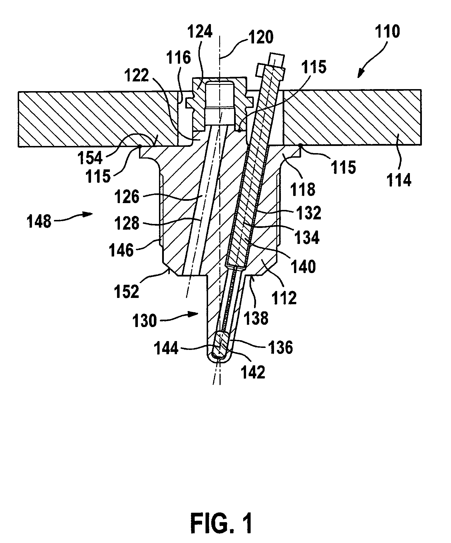
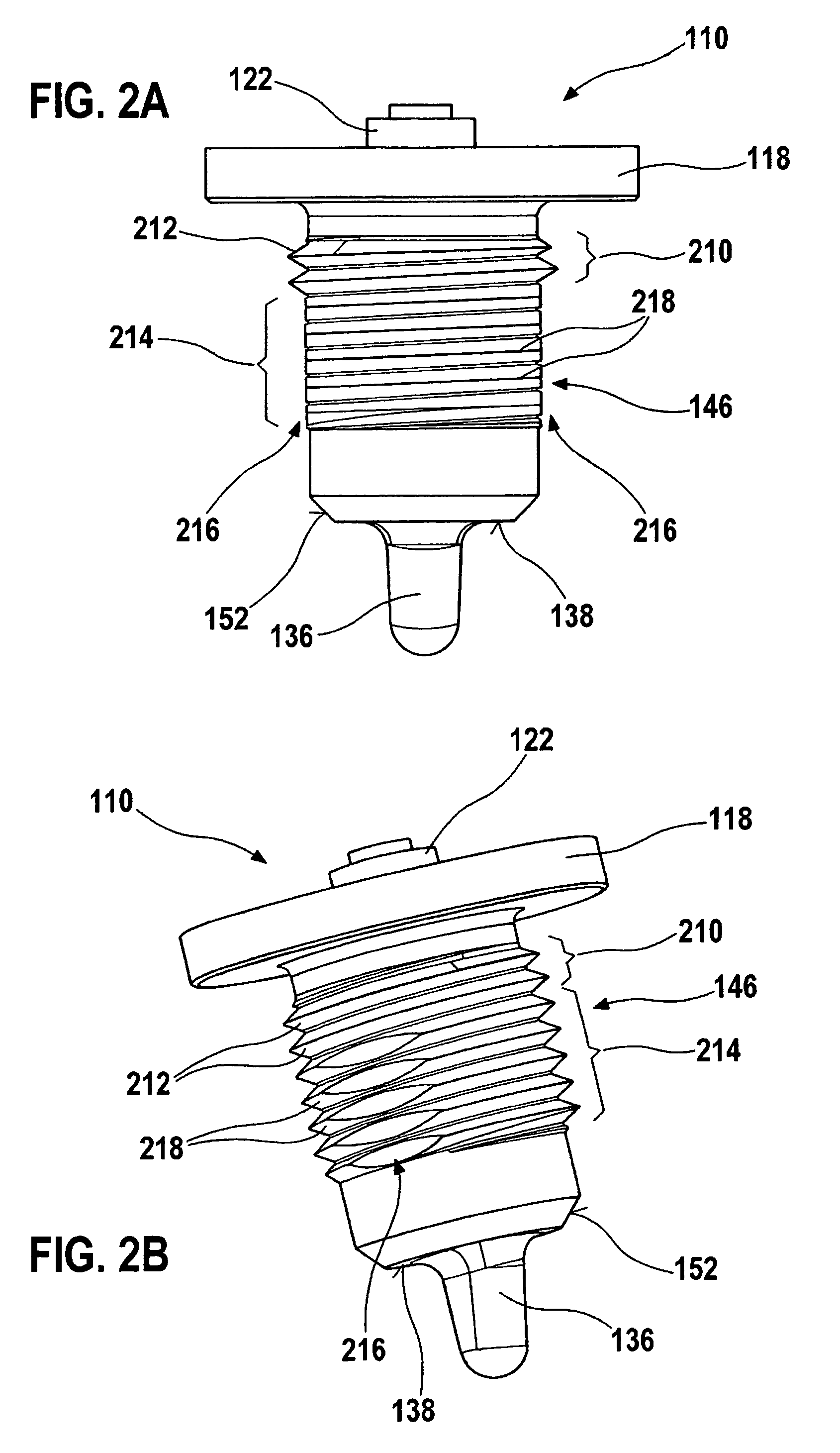
[0012]Minor interruptions, for example, by notches, may, however, be tolerable, in particular if these minor interruptions are covered by a threaded section above or below them. Therefore, also minor interruptions of this type are tolerable and are to be subsumed as “continuous.” However, the continuous thread need not be interrupted in any way. The first threaded section having at least one continuous thread thus protects the thread and the sealing surface of the plug-in sensor and the at least one sensor of the plug-in sensor against corrosive media and thus produces the required hermeticity and durability of the plug-in sensor.
[0013]Furthermore, in order to make it possible to introduce the plug-in sensor into the housing without problems, at least one second threaded section is provided. It includes at least one interrupted thread, this at least one interruption of the at least one interrupted thread forming a blow-out groove. This at least one blow-out groove, which may have two, three, four, or more blow-out grooves being provided, allows venting when the plug-in sensor is inserted into the housing and thus allows comfortable and smooth threading of the plug-in sensor into the housing. These blow-out grooves may be configured in such a way that they extend essentially (i.e., with a tolerance of + / −5 degrees, for example) parallel to a longitudinal axis of the plug-in sensor.
[0014]The at least one second threaded section may be situated between the at least one first threaded section and the sealing surface. In this way, the first threaded section effectively protects not only the sealing surface, but also the second threaded section. This at least one first threaded section may have between one and two continuous threaded sections. This refinement of the exemplary embodiments and / or exemplary methods of the present invention is advantageous in particular in connection with another refinement of the present invention in which the plug-in sensor is manufactured entirely or partly with the aid of a powder metallurgical method, in particular with the aid of a metal injection molding (MIM) method. Thus, in particular, the external thread may be entirely or partly manufactured by the powder metallurgical method, in particular with the aid of the metal injection molding method.
[0015]This refinement of the exemplary embodiments and / or exemplary methods of the present invention makes simple and cost-effective mass production in an injection molding process possible. Reworking (e.g., thread cutting) of the component is usually not required. When the threaded section is threaded into the housing, any burrs that may be present are sheared off. Due to what may be a preferred position of the continuous threads in the top area of the threaded section, shearing off does not result in increased threading torque. Two complete threads may still be manufactured to dimension and usually demolded without any problems.
[0018]The proposed plug-in sensor allows effective protection of the sealing surface and / or the remaining thread (depending on the position of the first threaded section) against corrosive media, without additional components (such as gaskets) being necessary therefor. A plurality of threaded sections may also be provided, for example, a first threaded section to protect the sealing surface and a second threaded section to protect other parts of the external thread against corrosive media. This permits, in particular by using the powder metallurgical method, a reliable, cost-effective, and durable plug-in sensor, which still meets or even exceeds all quality requirements, to be easily and rapidly manufactured. Complicated manual operations may be completely or partly omitted. The integrated splash protection or media protection by the at least one first threaded section considerably increases the service life compared to conventional plug-in sensors having continuous blow-out grooves. Thanks to this splash protection, splashing liquids are unable to reach the sealing surface, so that corrosion in this area is effectively prevented.
[0022]Furthermore, the sensor body may be designed in such a way that it has a sealing cone on its side facing the fluid medium. As is known from the related art, this sealing cone additionally enhances the seal of the plug-in sensor or the seal of the inner space against the outer space. In this way, the sealing cone cooperates reliably with the sealing surface separate from this sealing cone.

Problems solved by technology

The use of two separate sensors for detecting pressure and temperature represents a considerable degree of complexity, since at least two plugs and several cable bundles must be available.
Regarding hermeticity of the systems, leakages of less than 1 g per year are typically required.
These flattenings on the threads have, however, the disadvantage that liquid and / or gaseous corrosive media from the environment may reach the sealing surface via these flattenings.
For example, sensors of this type may be used in the engine compartment, so that oils, fats, engine cleaning agents, battery acid, and other types of impurities, which may occur in the surroundings of the engine, may reach and damage the sealing surface, thus reducing the reliability of the seal over the period of operation.

Method used


Image

  • Plug-in sensor for measuring at least one property of a fluid medium
  • Plug-in sensor for measuring at least one property of a fluid medium
  • Plug-in sensor for measuring at least one property of a fluid medium

Examples


Embodiment Construction

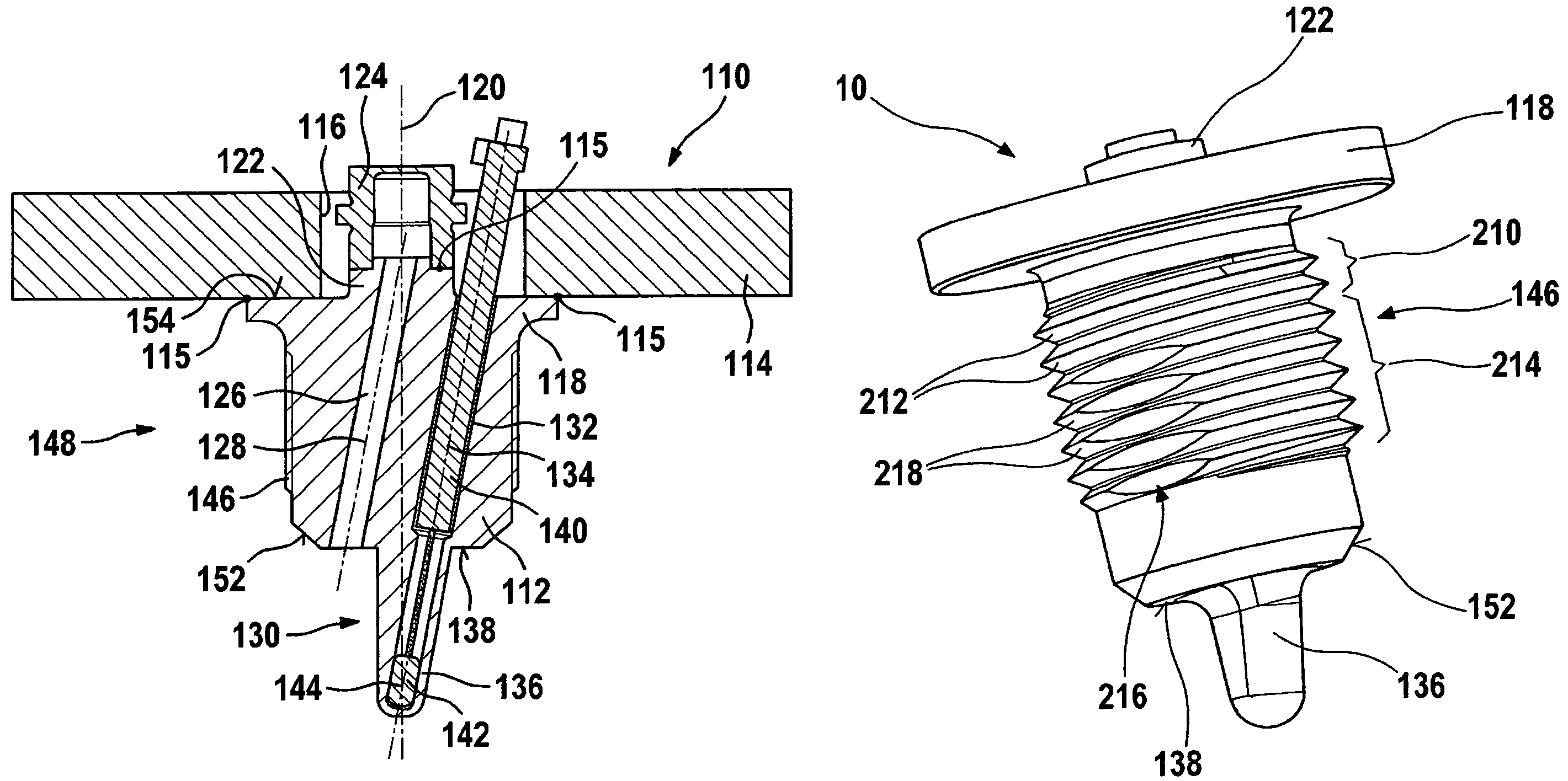
[0030]FIG. 1 shows an exemplary embodiment of a plug-in sensor 110 according to the present invention in a sectional view. Plug-in sensor 110 has a sensor body 112. A hexagonal body 114 having a central bore hole 116 is provided above sensor body 112. Sensor body 112 is connected to hexagonal body 114 which may be via an integral joint 115 (for example, a weld) in such a way that sensor body 112 is situated concentrically to central bore hole 116, and the top of sensor body 112 is accessible through central bore hole 116. In this way, electronic trigger components may be situated on the top of hexagonal body 114 in FIG. 1, for example, plug connections for contacting plug-in sensor 110.

[0031]The integral joints of the individual components are labeled in FIG. 1 by reference numeral 115 in general. For the purpose of an integral joint 115, sensor body 112 has on its top, between sensor body 112 and hexagonal body 114, a projection 118 facing hexagonal body 114 and having a contact su...


PUM

PropertyMeasurementUnit
temperaturesaaaaaaaaaa
angleaaaaaaaaaa
cone angleaaaaaaaaaa

Abstract

A plug-in sensor for measuring at least one property of a fluid medium, in particular for use in the coolant circuit of an air conditioning system of a motor vehicle. The plug-in sensor has at least one sensor for detecting the at least one property. Furthermore, the plug-in sensor has at least one sensor body having an external thread for threading the plug-in sensor into a threaded bore hole of a housing. Furthermore, the plug-in sensor includes a sealing surface for sealing an inner space of the housing against an outer space. The external thread has at least two threaded sections: a first threaded section including at least one continuous thread, and a second threaded section including at least one interrupted thread, at least one interruption of the at least one interrupted thread forming at least one blow-out groove.

Description

FIELD OF THE INVENTION[0001]The following description of the present invention relates specifically to applications in which a pressure (p) and a temperature (T) are to be measured, which is possible by using combined p-T sensors.BACKGROUND INFORMATION[0002]Parameters of fluid media, i.e., of gases and / or liquids, for example, must be measured in different industrial fields. Parameters of this type include, for example, a pressure, a temperature, a flow velocity, a density, or similar physical and / or chemical properties or parameters of the fluid medium.[0003]One important exemplary application of sensors of the above-mentioned type are pressure and temperature sensors for air conditioning systems. In air conditioning systems, the heat of evaporation of a coolant is normally used for cooling air (or another medium to be cooled). The coolant is then compressed in a compressor and thus liquefied. The coolant is heated when compressed. The absorbed heat is usually dissipated into the e...

Claims


Application Information

Patent Timeline
Patent Type & Authority Patents(United States)
IPC IPC(8): G01K1/00G01K13/00G01K7/00
CPCF16B33/02G01D11/245G01D11/30G01F1/36G01K1/08G01K13/02G01L19/003G01L19/0092G01F15/18Y10T29/49002
Inventor STOLL, OLIVERROESSER, CHRISTIANENGELHARDT, JOERG
Owner ROBERT BOSCH GMBH
Learn More