Modular clamp station

a module and clamping technology, applied in dough shaping, manufacturing tools, food shaping, etc., can solve the problems of undesirable deformation of the frame by the clamping force, heavy machines, and high maintenance costs of blow molding apparatuses described above, and achieve the effect of increasing the clamping for

Active Publication Date: 2013-06-04
GRAHAM ENG CO LLC
View PDF18 Cites 5 Cited by
  • Summary
  • Abstract
  • Description
  • Claims
  • Application Information

AI Technical Summary

Benefits of technology

[0007]An object of the invention is to provide a self-contained modular mold clamp assembly which in uncomplicated to remove and replace with another modular mold clamp assembly with minimal downtime for the rotary molding wheel, thereby minimizing the impact to the productivity of the operation.
[0008]Another object of the invention is to provide a modular mold clamp assembly which can be replaced by maintenance level personnel rather than factory technicians, thereby minimizing the cost.
[0009]Another object of the invention is to provide a simplified structure of a rotary molding wheel by using a modular mold clamp assembly which provides the structural support necessary between components of the rotary molding wheel.
[0011]Another object of the invention is to provide a modular mold clamp assembly which is lightweight.
[0012]Another object of the invention is to provide a modular mold clamp assembly which can be mounted to the rotary molding wheel in multiple configurations, allowing the rotary molding wheel to be configured to specific needs.
[0013]Another object of the invention is to provide modular mold clamping stations which can be used in tandem to accommodate large molds, to allow for even distribution of forces over the entire mold, and to prevent the end of the mold halves from separating when the parison is introduced into the mold cavity.

Problems solved by technology

Deformation of the frame by the clamp force is undesirable because deformation would not permit the mold faces to close parallel with one another.
The blow molding apparatuses described above are typically costly, heavy machines, which require a good deal of expertise to maintain.
In addition, if the number of mold clamps of the blow molding apparatus are to be changed to accommodate molds of a different size, the cost and time required to disassemble and reassemble the apparatus is significant.

Method used


Image

  • Modular clamp station
  • Modular clamp station
  • Modular clamp station

Examples


Embodiment Construction

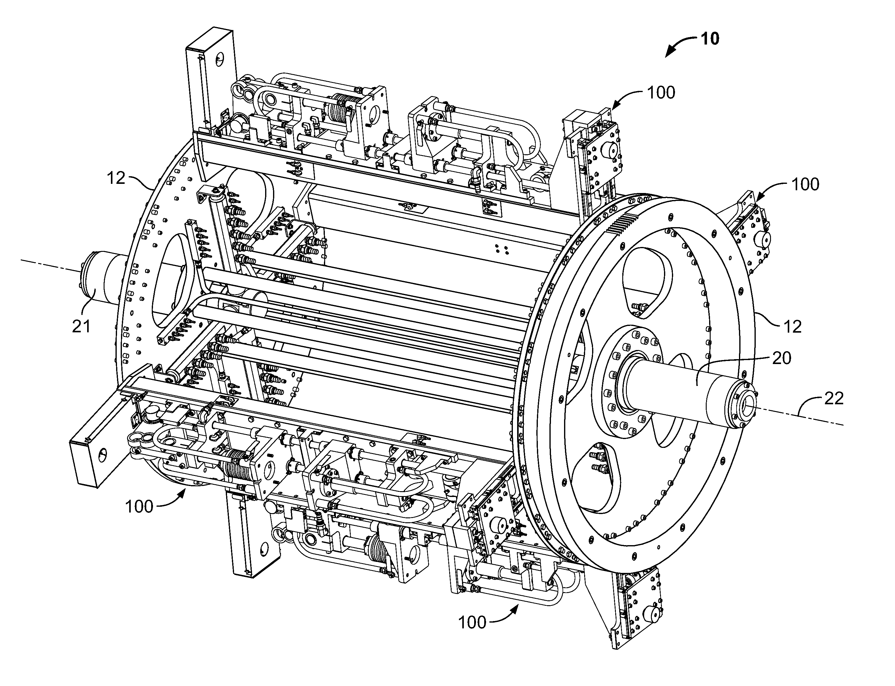
[0030]Referring to FIGS. 9-11, a wheel 10 of a blow molding machine is illustrated. However, the invention is not limited to a blow molding machine, as other molding machines can be used without departing from the scope of the invention. The blow molding machine has a base (not shown) upon which the wheel 10 is rotatably supported. An extruder (not shown) is positioned adjacent the wheel 10. The wheel 10 has two essentially parallel radially extending plates or turntables 12 which carry a plurality of modular mold clamp assemblies 100, each having an inner cavity (not depicted) to receive a parison from the extruder. The wheel 10 is mounted on a shafts 20, 21 which has a drive which rotates the wheel 10 and modular mold clamp assemblies 100 about a rotational axis 22 of the wheel 10 and the shafts 20, 21 to direct each mold secured by the modular mold clamp assemblies 100 between extrusion, blow molding, cooling and ejection stations, as is known in the art. In the depicted embodime...


PUM

PropertyMeasurementUnit
movementaaaaaaaaaa
transmitting forcesaaaaaaaaaa
clamping forceaaaaaaaaaa

Abstract

A modular mold clamp assembly for use in a molding machine. The assembly has a frame with a base member and oppositely-facing end members, with the oppositely-facing end members having mounting areas provided thereon. First and second platens are movably mounted on the base member between an open and a closed position. The platens are mounted on the frame and are movable relative to the frame without transmitting forces to the frame. The frame, containing the platens, can be mounted or unmounted to the molding machine by the use of mounting hardware cooperating with the mounting area of the frame.

Description

FIELD OF THE INVENTION[0001]The invention relates generally to an extrusion molding apparatus. Specifically, the present invention relates to modular mold clamping assemblies for use with the molding apparatus.BACKGROUND OF THE INVENTION[0002]Conventional rotary extrusion blow molding apparatuses typically have a structural frame mounted on a rotating shaft. The structural frame has a plurality of molds mounted thereon and is known in the industry as a wheel. As the wheel is rotated, the plurality of molds is rotated past an extrusion die extruding a continuous parison. Each mold typically includes two mold halves, each comprising a mold cavity half therein, such that when the mold halves are closed, the mold defines a mold cavity corresponding to the configuration of the article to be molded, such as a container. Each mold, seriatim, is rotated past the extrusion die with the mold halves in an open configuration. The mold halves of each mold are then closed around the parison to en...

Claims


Application Information

Patent Timeline
Patent Type & Authority Patents(United States)
IPC IPC(8): B29C49/36B29C49/56
CPCB29C49/56B29C49/36B29C49/04B29C49/5602B29C49/5603B29C49/561B29C33/22B29C33/36
Inventor MATHY, JR., JOHN M.OLES, PAUL M.FIORANI, DAVID N.
Owner GRAHAM ENG CO LLC
Why Eureka
Try Eureka