
Surgical suturing clamp

a clamp and suturing technology, applied in the field of surgical instruments, can solve the problems of causing trauma traumatic method of constriction or ligation, and compressive load applied to the suturing conduit, so as to reduce the twisting of the suturing conduit, reduce the shearing action, and reduce the effect of ligating the anatomic condui

Active Publication Date: 2013-06-04
CORONEO
View PDF18 Cites 51 Cited by
  • Summary
  • Abstract
  • Description
  • Claims
  • Application Information

AI Technical Summary

Benefits of technology

The invention is a simple and reliable device that is easy to use. It has wire-like parts that can be opened and closed with a single action. This makes it easy to position the device correctly. The device is designed to partially or fully ligate anatomical structures without causing any damage or discomfort.

Problems solved by technology

When fragile anatomic conduits are involved, such a method of constriction or ligation tends to be traumatic.
Pulling the loose ends of the surgical suture induces a tension in the surgical suture and results in a compressive load applied to said conduit.
The non-elastic nature of a surgical suture, and its generally thin cross-section relative to the anatomic conduit, tends to induce trauma to the said conduit.
However, these elastic ligatures tend to dig into a body tissue or anatomic conduit if they become twisted during their deployment.
This may lead to unwanted tissue trauma.
As such, the interior surface of the surgical loop does not easily come into contact with itself, thereby tending to reduce the likelihood of twisting said surgical loop during its deployment.
This method represents an inefficient use of the surgical assistant's time and tends to be cumbersome and non-ergonomic for the surgeon.
This tends to compromise the ergonomics of the surgical window, and the surgeon's access thereto.
In certain instances, this may lead to trauma of the coronary artery by virtue of extensive external snaring.
This shearing action may induce a trauma to the anatomic conduit as it may cause it to twist and assume a tortuous configuration.

Method used


Image

  • Surgical suturing clamp
  • Surgical suturing clamp
  • Surgical suturing clamp

Examples


first embodiment

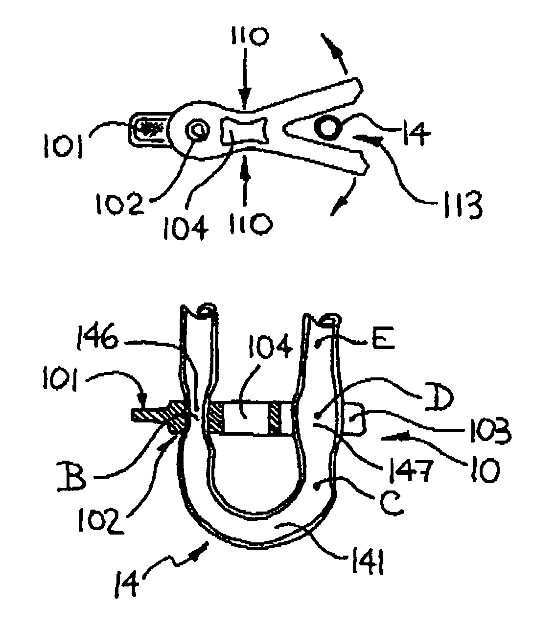
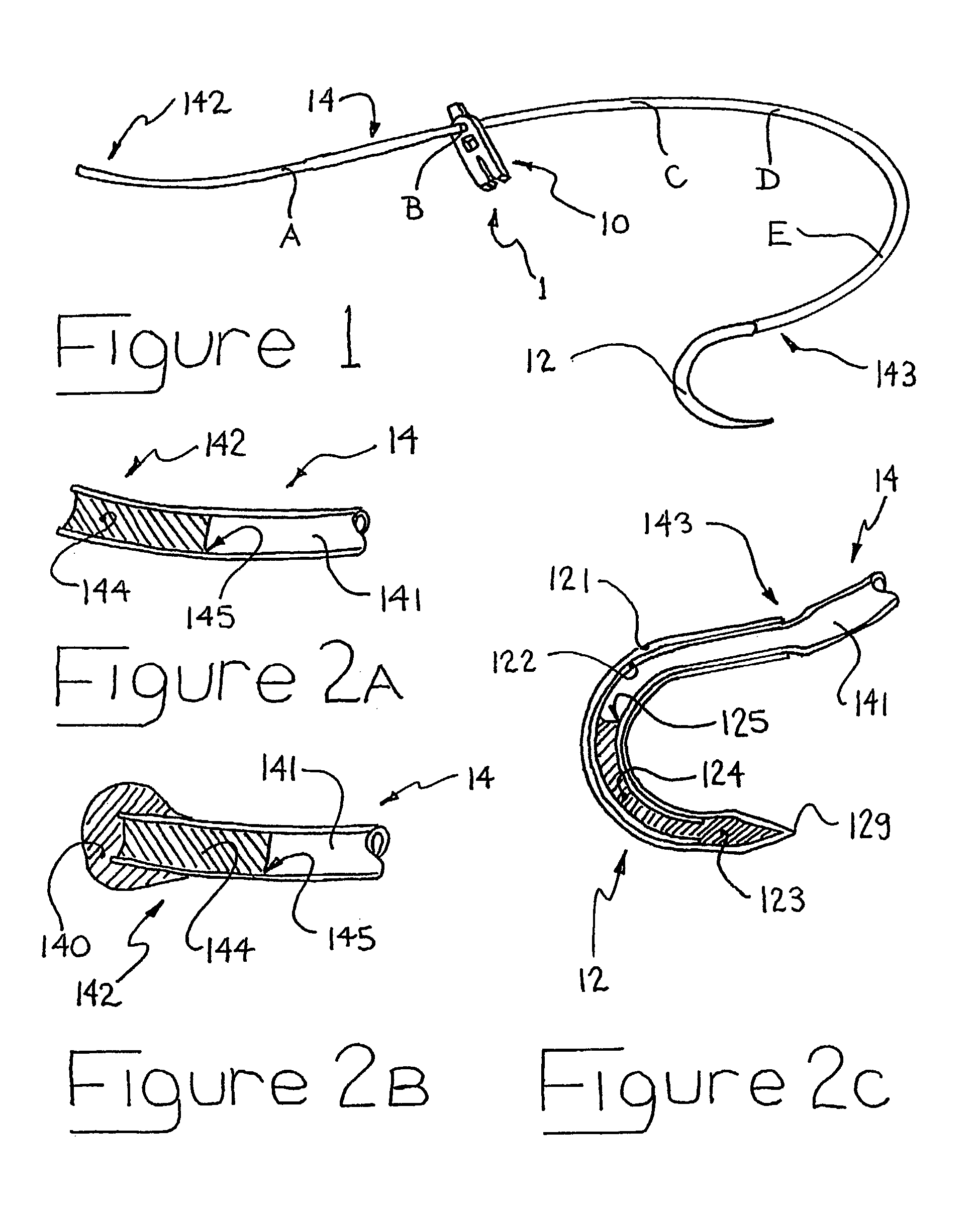
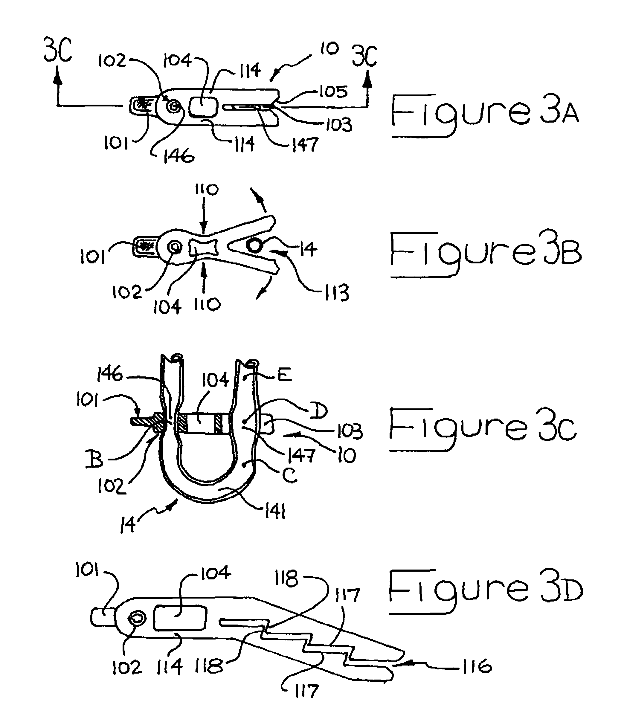
[0083]By way of a general overview and with reference to FIG. 1, a surgical loop 1 is comprised of a holding member such as for example a pledget 10, a tissue-piercing means such as for example a needle 12, and a wire-like member such as for example a substantially tubular body 14.

[0084]Tubular body 14 is preferably made from an elastomeric material and is configured with a lumen 141 extending through out most of its length, between its free end 142 and its needle-engaging end 143. Free end 142 is sealed with a substantially fluid-tight seal 145 to prevent air trapped within lumen 141 from escaping. Fluid-tight seal 145 is achieved by an elastomeric plug 144, preferably made of a similar elastomeric material to the tubular body, and extending a small distance inwardly from end 142 into lumen 141 of tubular body. An example of a suitable elastomeric material is silicone elastomer, with the silicone hardening and adhering to the tubular body 14 upon curing. The silicone used is prefer...

third embodiment

[0112]To deform slot 305 into its open configuration, a compressive force 310 is applied to slot 303. As a result, arm 313 is brought closer to pledget body 307 while arm 317 is simultaneously moved away from pledget body 307. In order for slot 305 to assume its open configuration, slot 303 is compressed beyond its biased-closed configuration, up to a point when arm 313 comes into contact with pledget body 307. Said compressive force is preferably applied by the jaws of a forceps 399, or other like surgical implement. One said jaw is placed into contact with the ending most portion of arm 313 while the other cooperating jaw is placed into contact with lateral face 317 of pledget 30. Ending-most portion of arm 313 is preferably configured with a substantially flat surface 314, which is substantially parallel to lateral face 317 of pledget 30. Surface 314 and lateral face 317 may also be provided with a rough texture to encourage slip-free engagement with the jaws of forceps 399. Bias...

second embodiment

[0114]Pledget 40 is preferably manufactured from a substantially non-deformable polymeric material, approved for surgical use. Pledget 40 is substantially elongate in shape, with a fence 406 disposed along non-contact surface 408 of pledget 40. Fence 406 preferably assumes a substantially perpendicular orientation relative to the longitudinal axis of pledget 40, and a substantially parallel orientation relative to longitudinal axis of anatomic conduit AC when said pledget 40 is fully deployed. Fence 406 protrudes from non-contact surface 408 a sufficient amount, such that a slot 403 of sufficient depth to engage a sufficient width of tubular body 14, may be configured therewithin. Alternatively, a thicker pledget 40, at least as thick as the protrusion of fence 406, may be used. This results in a pledget with a substantially flat non-contact surface 408 that is interrupted by opening 402 and slot 403. Slot 403 is configured with a chamfer 405 that spans along the open end of slot 40...


PUM


Abstract

A surgical loop for constricting or ligating, partially or fully, an anatomic conduit during a surgical intervention. The surgical loop includes an elastomeric tubular body, a curved needle that is attached to one free end of the tubular body to facilitate its insertion through a body tissue containing an anatomic conduit, and a pledget which is frictionally engaged and positionable along the length of the tubular body. The pledget is frictionally engaged with a first portion of the tubular body through a closed-perimeter opening. A second portion of the tubular body is subsequently frictionally engaged or restrained with the pledget through a slot. The pledget is configured with a bias structure which maintains the slot in a biased-closed configuration to engage and restrain the second portion of tubular body.

Description

FIELD OF THE INVENTION[0001]The present invention relates to the field of surgical instruments and more specifically, to a surgical loop and procedure for partially or fully constricting an anatomic conduit, or displacing or restraining a body tissue.BACKGROUND OF THE INVENTION[0002]During the course of a surgical procedure, it is often required to displace or restrain a body tissue. This tends to facilitate surgical access to the target anatomic tissue in need of the surgical intervention, which is contained in the displaced or restrained body tissue. Alternatively, a body tissue may be displaced or restrained away from the site of a surgical intervention in which the target anatomic tissue is situated.[0003]During many types of surgical interventions, it is also often required to constrict or ligate, either partially or fully, an anatomic conduit in order to restrict or prevent flow through said anatomic conduit, during at least a duration of the surgical intervention. For instanc...

Claims


Application Information

Patent Timeline
IPC IPC(8): A61B17/08F16G11/00A61B17/04A61B17/06A61B17/12
CPCA61B17/0487A61B17/12009A61B2017/0406A61B2017/0454A61B2017/0464A61B2017/06028Y10T24/3916
Inventor PAOLITTO, ANTHONYVALENTINI, VALERIOCARTIER, RAYMOND
Owner CORONEO
Learn More