
Optical waveguide, optical waveguide module, and electronic apparatus

a technology of optical waveguide and light guide, which is applied in the direction of fixed installation, lighting and heating apparatus, instruments, etc., can solve the problems of increasing coupling loss, increasing coupling loss, and reducing the light quantity of the light received by the light receiving portion, so as to achieve stable light transmission, suppress the fluctuation amount of light loss in light transmission, and stable light transmission

Inactive Publication Date: 2013-06-04
ORMON CORP
View PDF10 Cites 0 Cited by
  • Summary
  • Abstract
  • Description
  • Claims
  • Application Information

AI Technical Summary

Benefits of technology

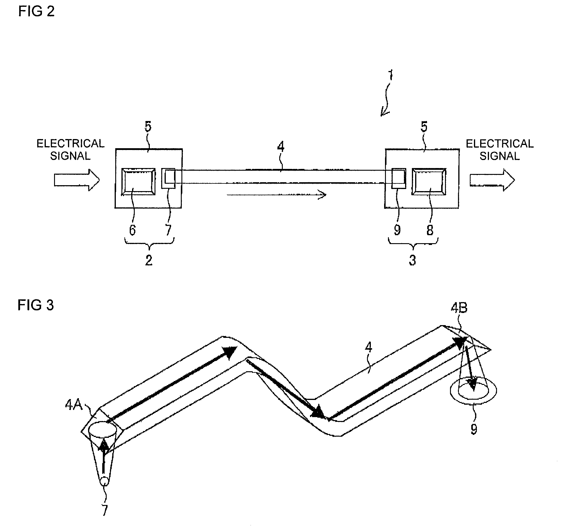
The conventional light guide module has a problem where the position of the light incident surface and the range of the light emitted from the light emitting portion fluctuates, reducing the amount of light that enters the light guide. This results in a coupling loss of light and makes it difficult to transmit stable light. However, the patent proposes a new configuration where the light emitting portion and the light receiving portion are arranged in the lateral direction in relation to the light guide. This makes it easier to mount and can be more miniaturized. Overall, the patent aims to address the problem of reduced light quantity and coupling loss in conventional light guide modules.

Problems solved by technology

If the light quantity of the light introduced into the light guide reduces due to the coupling loss, the light quantity of the light received by the light receiving portion is also reduced, and thus stable light transmission becomes difficult.
Thus, in the conventional light guide module, the coupling loss increases and fluctuates due to variation and the like in mounting, and a stable light transmission becomes difficult.
Furthermore, if the light emitting amount from the light emitting portion is increased to correct the reduction in the light receiving amount at the light receiving portion that occurs by the coupling loss, the power consumption increases.
Moreover, a feedback circuit is required to perform a stable light transmission, whereby the development period extends, the IC cost increases, and the system power consumption increases.

Method used


Image

  • Optical waveguide, optical waveguide module, and electronic apparatus
  • Optical waveguide, optical waveguide module, and electronic apparatus
  • Optical waveguide, optical waveguide module, and electronic apparatus

Examples


application example

[0142](Application Example)

[0143]The light guide 4 of the present embodiment can be applied to the following application examples.

[0144]First, as a first application example, use can be made at a hinge portion in a foldable electronic device such as a foldable portable telephone, a foldable PHS (Personal Handyphone System), a foldable PDA (Personal Digital Assistant), and a foldable notebook computer.

[0145]FIGS. 16(a) to 16(c) show an example in which the light guide 4 is applied to a foldable portable telephone 40. In other words, FIG. 16(a) is a perspective view showing an outer appearance of the foldable portable telephone 40 incorporating the light guide 4.

[0146]FIG. 16(b) is a block diagram of a portion where the light guide 4 is applied in the foldable portable telephone 40 shown in FIG. 16(a). As shown in the figure, a control unit 41 arranged on a body 40a side in the foldable portable telephone 40, an external memory 42, a camera (digital camera) 43, and a display unit (liq...


PUM


Abstract

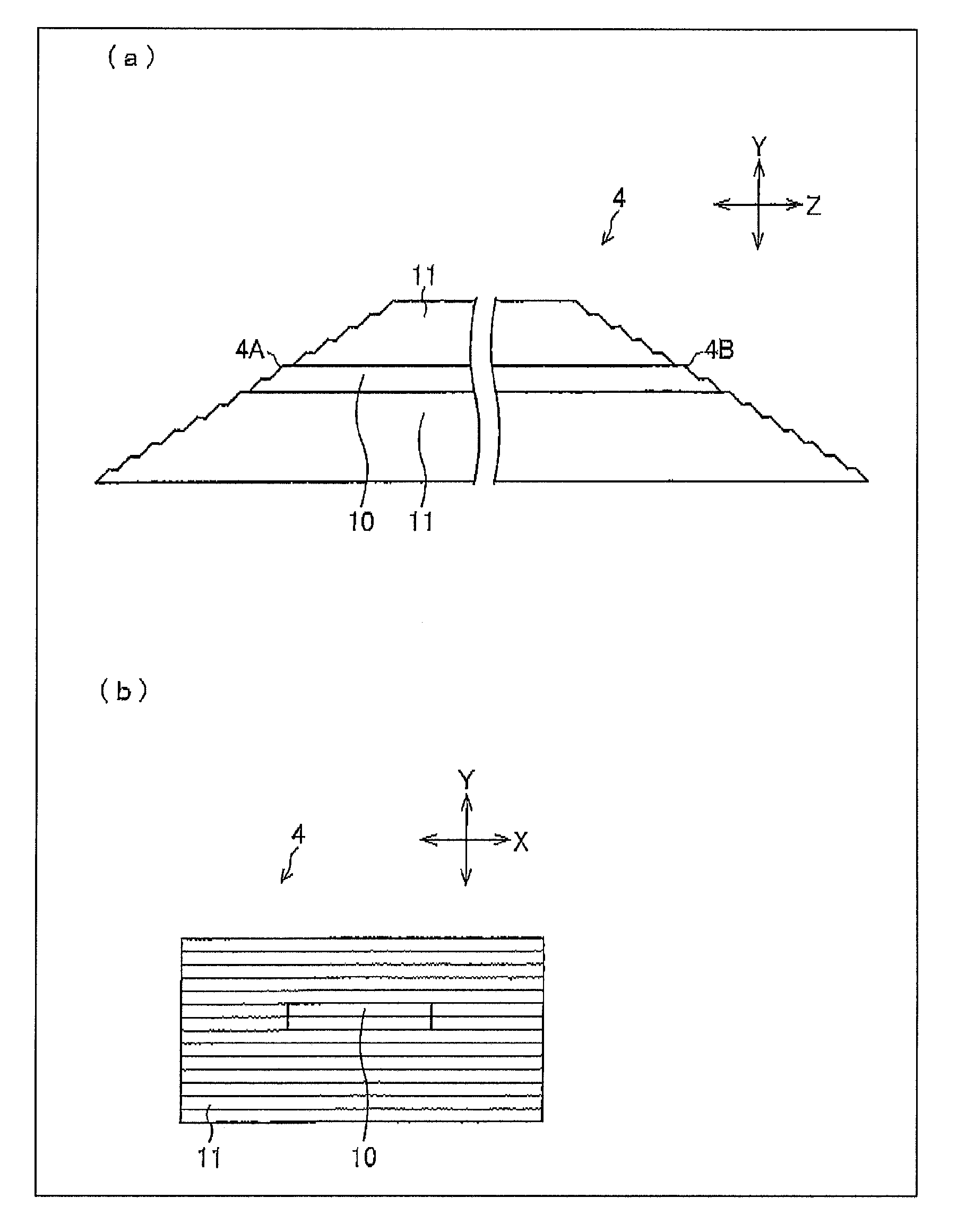
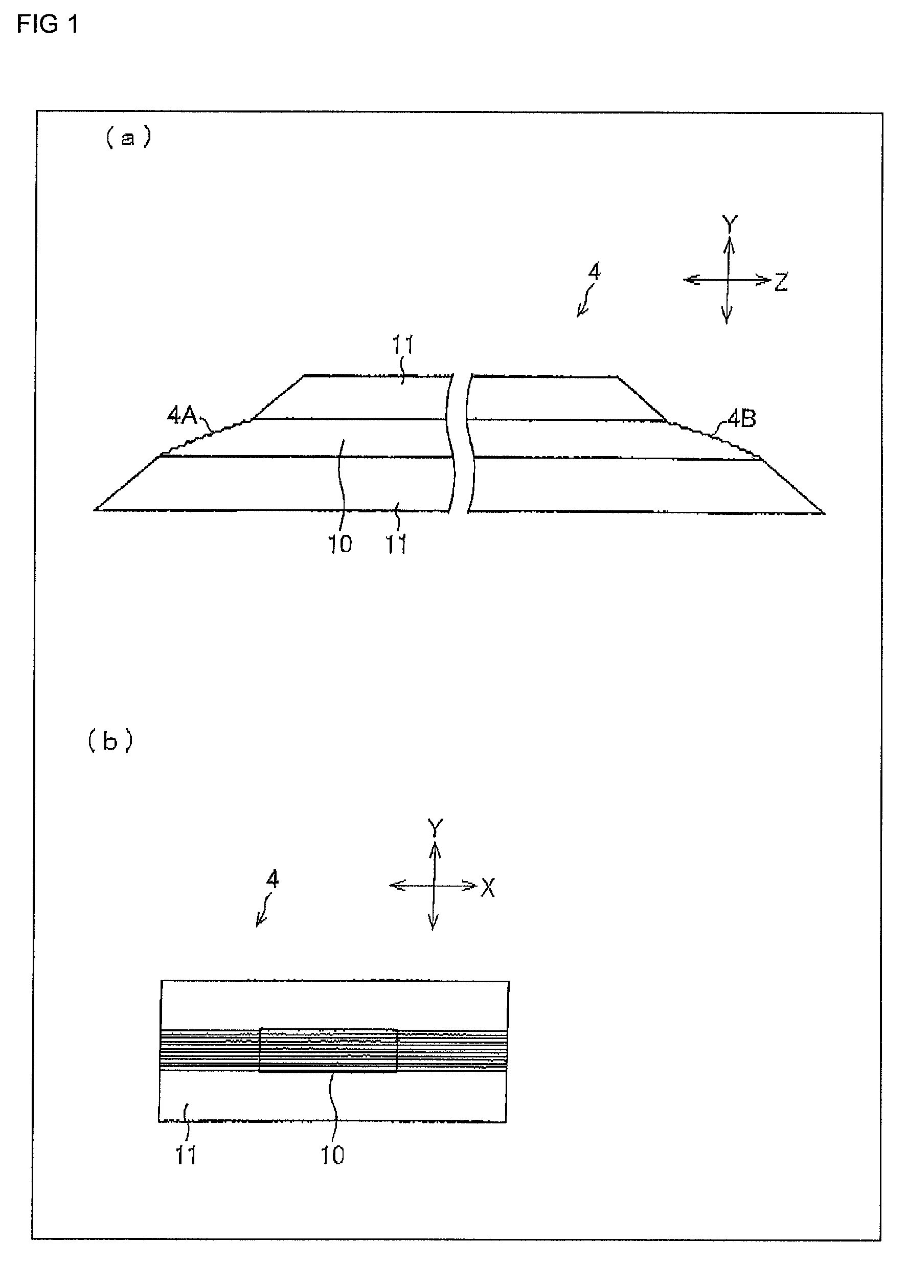
A light guide includes a core and a clad made of a material having an index of refraction different from an index of refraction of the core and covering the core, in which at least one of a light incident surface or a light exit surface of the core is arranged while shifted in parallel without changing respective inclined angles so that the inclined surface is divided into a plurality of inclined surfaces parallel in a longitudinal direction (X direction) of the rectangular shape in the orthogonal projection and the plurality of inclined surfaces closer to the light emitting portion are positioned in a direction (Z direction) of moving away from the end face to be in a shape extending in the direction (Z direction) of moving away from the end face in a stepwise manner as a whole.

Description

TECHNICAL FIELD[0001]The present invention relates to a light guide for transmitting an optical signal, a light guide module, and an electronic device.BACKGROUND ART[0002]In recent years, an optical communication network enabling large capacity data communication at high speed is expanding. The optical communication network is assumed to be mounted from intra-devices to inter-device in the future. A light guide that can be arrayed is expected to realize the print wiring substrate as an optical wiring.[0003]The light guide has a double structure of a center core, which is called a core, and a capsule, which is called a clad, that covers the core, where the index of refraction of the core is higher than the clad. In other words, the optical signal entered to the core is propagated by repeating total reflection inside the core.[0004]In recent years, in particular, realization of a flexible optical wiring mounted on a smaller and thinner commercially-off-the-shelf device with the light ...

Claims


Application Information

Patent Timeline
Patent Type & Authority Patents(United States)
IPC IPC(8): G02B6/42G02B6/02
CPCG02B6/4214G02B6/43G02B6/122G02B6/42
Inventor TERAKAWA, YUKARIHOSOKAWA, HAYAMI
Owner ORMON CORP
Learn More