Global positioning tag system and method

Inactive Publication Date: 2013-06-04
CSR TECH INC
View PDF31 Cites 0 Cited by
  • Summary
  • Abstract
  • Description
  • Claims
  • Application Information

AI Technical Summary

Benefits of technology

The present invention provides a system and method for determining the position and velocity of an object using multiple GPS signals. The system includes an interrogator and a transponder. The interrogator is remote from the object and receives GPS signals. It transmits an RF signal with GPS source information and other information about the GPS signals. The transponder is positioned on the object and receives the RF signal. It tracks one of the GPS signals and generates a correlation snapshot. The snapshot is transmitted to the interrogator. The interrogator processes the snapshot to determine the position and velocity of the transponder. The invention allows for accurate positioning and tracking of objects using GPS signals.

Problems solved by technology

The barge environment is low in vibration and dynamics, but the unit can be expected to be dropped and mishandled during transport.
This system for providing a DGPS tag for a remote unpowered object is undesirable in that all the equipment must be powered continuously.
Thus the system consumes a large amount of power.
While this application has the lowest power requirements, it must transfer large amounts of data which presents its own troubles in terms of complexity and reliability.
What has been needed and heretofore unavailable is a system with very low power, requirements that is small and easy to deploy.

Method used


Image

  • Global positioning tag system and method
  • Global positioning tag system and method
  • Global positioning tag system and method

Examples


Embodiment Construction

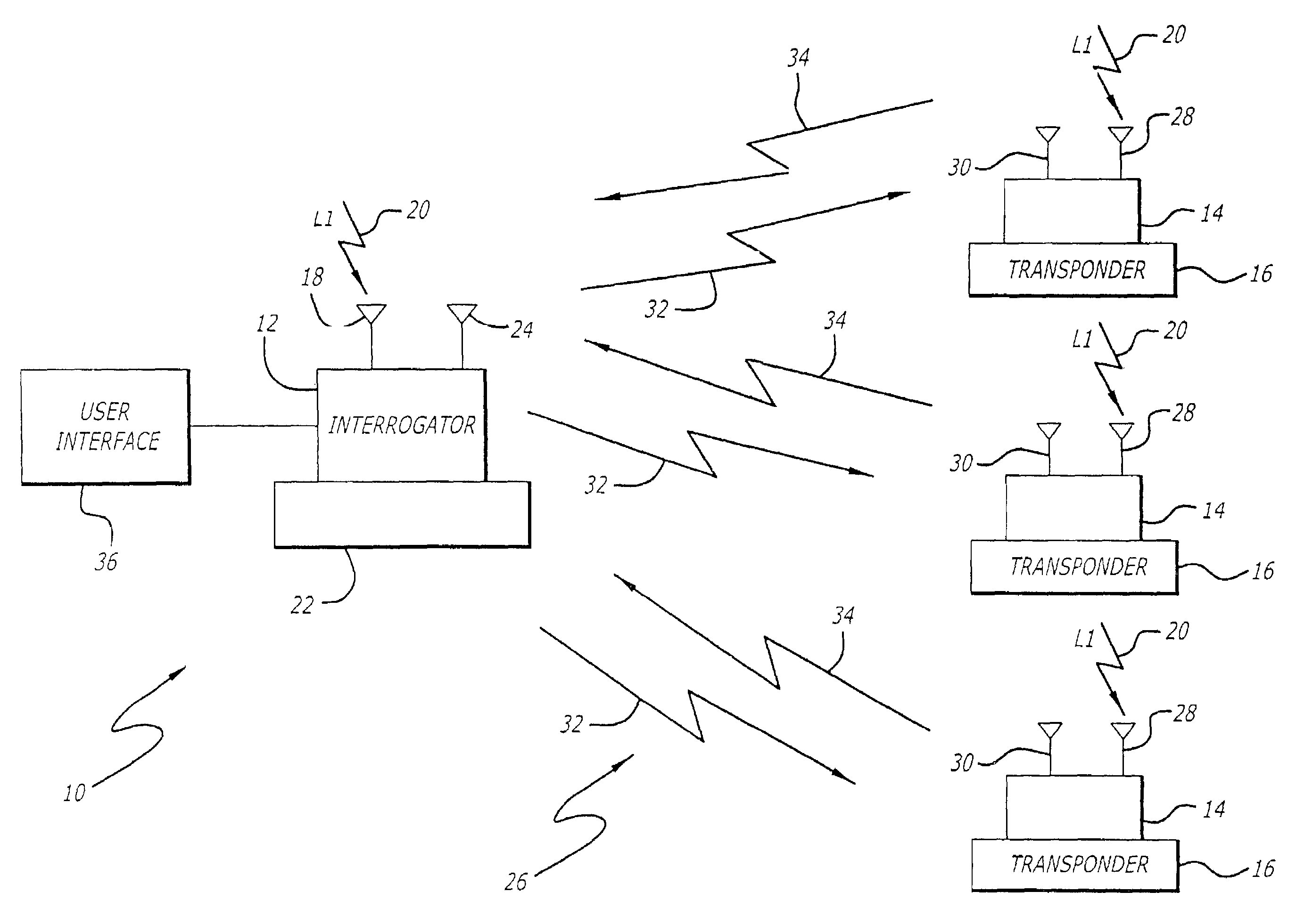
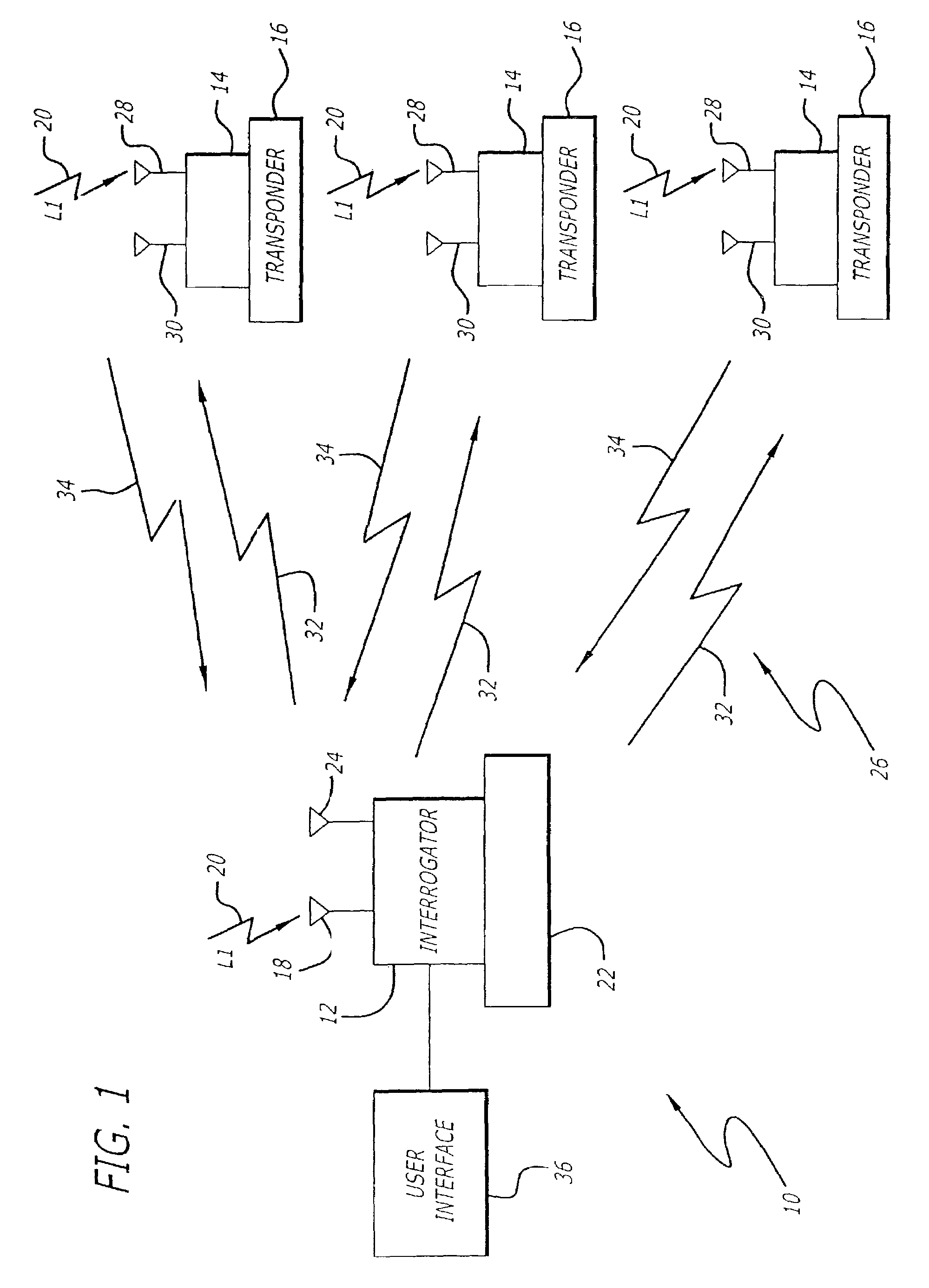
[0022]Turning now to the drawings, in which like reference numerals are used to designate like or corresponding elements among several figures, in FIG. 1 there is shown a functional block diagram of a GPS tag system 10 in accordance with aspects of the present invention. The GPS tag system 10 may be used in various applications in which the position and velocity of an object 16 is desired to be known. The following description of the invention focuses on the use of the GPS tag system 10 as a means of tracking the position of a barge being towed by a towing vessel. The invention, however, is by no means limited to this application.

[0023]Returning to FIG. 1, the GPS tag system 10 includes an interrogator 12 located on a base object 22 and at least one transponder 14, also referred to herein as a “tag”, placed on a remote object 16 where power may or may not be available. The interrogator 12 includes a receiving antenna 18 for receiving GPS signals 20 transmitted by one or more GPS sou...


PUM


Abstract

A system for determining the location of an object includes an interrogator remote from the object and a transponder located at the object. The interrogator receives GPS signals and transmits pre-positioning data and a tracking signal to the transponder. The pre-positioning data includes pseudorandom noise (PRN) code number, Doppler frequency offset and code phase offset while the tracking signal includes reference time and frequency information. The transponder collects RF samples of at least one of the GPS signals associated with one of the PRN code numbers and correlates the RF samples of the GPS signal against code replicas of the GPS signal based on the Doppler frequency offset, code phase offset and reference time and frequency information for that GPS signal to produce the correlation snapshot. The transponder transmits the correlation snapshot to the interrogator and the interrogator determines the pseudorange associated with the GPS signal using the correlation snapshot.

Description

RELATED APPLICATIONS[0001]This is a continuation of application Ser. No. 10 / 156,492, filed May 28, 2002, now U.S. Pat. No. 6,611,757, which is continuation of application Ser. No. 09 / 903,934, filed Jul. 12, 2001, now U.S. Pat. No. 6,427,121, which is a continuation of application Ser. No. 09 / 560,797, filed Apr. 28, 2000, now U.S. Pat. No. 6,301,545, which claims the benefit of provisional application Ser. No. 60 / 132,046 filed Apr. 30, 1999.BACKGROUND OF THE INVENTION[0002]1. Field of the Invention[0003]This invention relates generally to a position measuring device and more particularly to a system that uses Global Positioning System (GPS) satellites to determine the position of an object.[0004]2. Description of the Related Art[0005]It is often desirable to obtain the position and velocity of an object such as an unmanned vessel. Such objects or vessels include, for example, towed barges, aircraft and automobiles. With respect to a towed barge, the reasons for obtaining the position...

Claims


Application Information

Patent Timeline
IPC IPC(8): G01C21/00G01S1/00G01S5/14G01S11/02G01S13/75G01S13/76G01S13/79G01S19/05G01S19/14G01S19/17G01S19/25G01S19/30G01S19/34G01S19/43G01S19/52G08G1/13
CPCG01C21/005G01S5/0036G01S11/02G01S19/05G01S19/09G01S19/235G01S19/254G01S19/256G01S19/30G01S19/43G01S19/52G01S13/758G01S19/34
Inventor BRODIE, KEITH J.
Owner CSR TECH INC
Why Eureka
Try Eureka