Circuit for adaptive sampling edge position control and a method therefor

a position control and sampling edge technology, applied in the field of electronic circuits, can solve problems such as signal degradation, simple compensation techniques such as simple correction of path frequency response such as boosting the high frequency components of signals, and insufficient to deal with high speed signals that may be severely degraded, and achieve the effect of reducing the number of signals in the system, and improving the quality of signals

Active Publication Date: 2006-02-16
MACOM CONNECTIVITY SOLUTIONS LLC
View PDF11 Cites 77 Cited by
  • Summary
  • Abstract
  • Description
  • Claims
  • Application Information

AI Technical Summary

Benefits of technology

[0073] The CDR as described above may be formed on a single semiconductor substrate and manufactured in bipolar or MOSFET technology. The CDR, the sampling edge position control circu

Problems solved by technology

Ideally, the BER is 0, but a number of impairments can affect the propagation of the signal resulting in signal degradation.
Simple techniques of compensation, for example simple correction of the path frequency response such as boosting the high frequency components of the signal, are not adequate for dealing with high speed signals that may be severely degraded.
A well known source of degradation in many communications systems is dispersion.
The received signal is affected by the sum of these components, resulting in inter symbol interference (ISI) by spreading the energy of each optical pulse over neighboring bits.
The dispersion can thus cause bit errors in the receiver by confusing 1s and 0s.
Dispersion is present in all optical systems, but its effects become worse over longer spans and at higher transmission speeds.
While this method may theoretically be used to realize high-accuracy compensation for waveform degradation of a received signal stemming from chromatic dispersion, polarization mode dispersion or the like without employing a dispersion compensation fiber or a polarization maintaining fiber, it is an expensive

Method used


Image

  • Circuit for adaptive sampling edge position control and a method therefor
  • Circuit for adaptive sampling edge position control and a method therefor
  • Circuit for adaptive sampling edge position control and a method therefor

Examples


Embodiment Construction

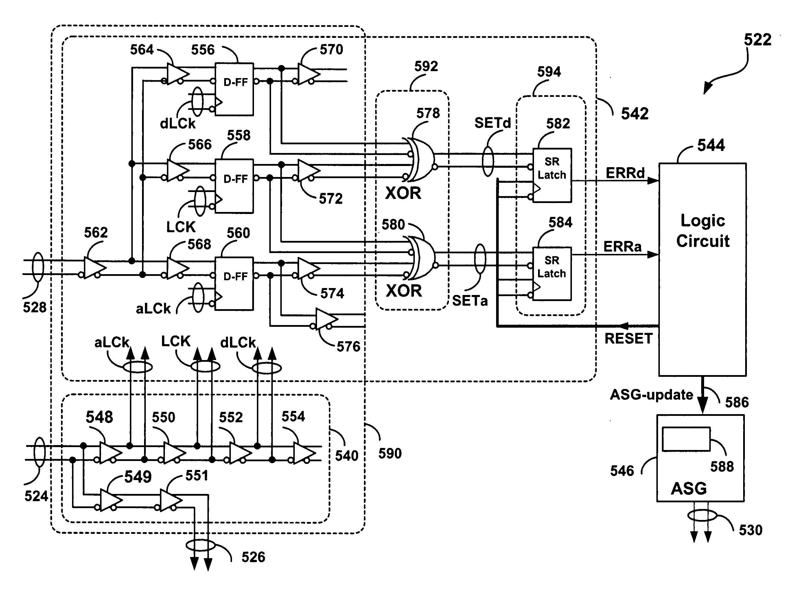
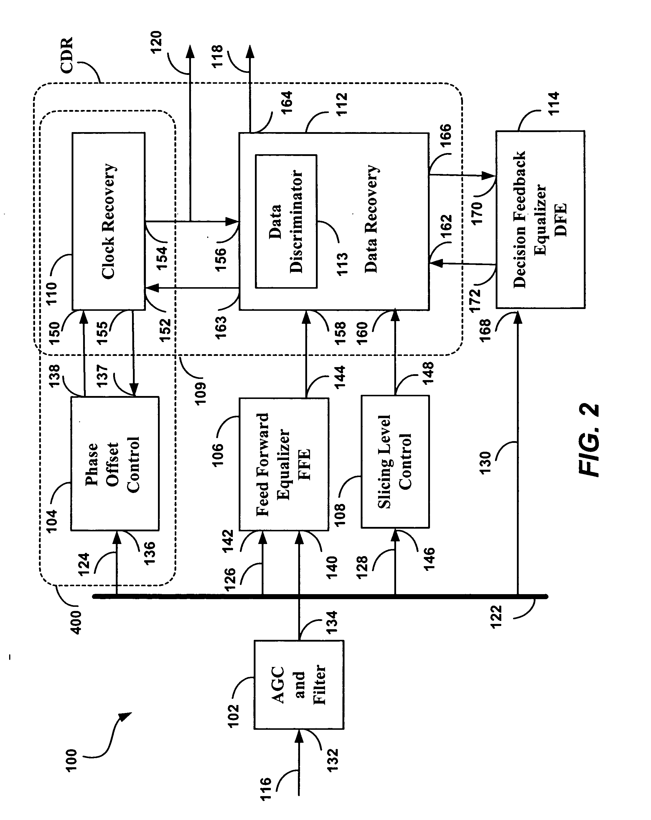
[0086] The present invention is concerned with the automatic adaptation of the sampling edge position for a Clock and Data Recovery (CDR) having clock-to-data phase offset control.

[0087] For an undistorted signal, symmetrical on the vertical axis, the optimum eye sampling time (sampling edge position) will be in the middle of the eye, at 50%. For a distorted eye, performance can be improved by shifting the sampling point away from the eye center. This is accomplished using a sampling edge position control or phase offset (offset from the eye center) control circuit incorporated in the clock and data recovery block (CDR).

[0088] An Adaptive Sampling Edge Position Control Circuit and method have been developed, which may be incorporated into a CDR circuit having phase offset control. It is understood that the sampling edge position detection circuit of the embodiment of the present invention, providing a capability for improved and adaptive sampling edge position. This may be used in...


PUM


Abstract

A clock and data recovery circuit (CDR) for receiving high-speed digital data, and having an analog phase offset control capability, is improved by providing an adaptive sampling edge position control. A differential circuit samples the raw data signal at three closely spaced sampling points of the eye, and compares advanced and delayed sampled data with the nominal sampled data. If either the advanced or delayed sampled data differ from the nominal sampled data, i.e. if advanced or delayed errors are detected, a shift in the sampling edge position may be required. A logic circuit performs a method determining the occurrence of advanced or delayed errors over progressively longer time intervals, and to adjust the sampling edge position of the CDR by controlling the phase offset.

Description

RELATED APPLICATIONS [0001] The present application claims the benefit of U.S. Provisional Application Ser. No. 60 / 599,946 to Popescu et al, filed on Aug. 10, 2004, and entitled “A Circuit for Improved Sampling Edge Position Detection and a Method Therefor”.FIELD OF INVENTION [0002] The invention relates to electronic circuits, and in particular to a method for adaptively controlling the sampling edge position of a high speed signal and a circuit therefor. BACKGROUND OF THE INVENTION [0003] In digital communications systems comprising transmission links, it is a primary goal to recover the transmitted data as faithfully as possible at the receiving end of a link. The bit error rate (BER) is an indication commonly used to characterize such systems. [0004] Ideally, the BER is 0, but a number of impairments can affect the propagation of the signal resulting in signal degradation. Simple techniques of compensation, for example simple correction of the path frequency response such as boo...

Claims


Application Information

Patent Timeline
IPC IPC(8): H04L27/22H04L7/02
CPCH03L7/087H03L7/0896H04L25/069H04L7/033H03L7/091
Inventor POPESCU, PETREMCPHERSON, DOUGLAS STUARTQUOC, HAI TRANWOLSKI, STANISLAS
Owner MACOM CONNECTIVITY SOLUTIONS LLC
Why Eureka
Try Eureka