Frequency offset compensating apparatus and method, and optical coherent receiver

a frequency offset compensation and frequency offset compensation technology, applied in the field of optical communication, can solve the problems of difficult realization of the receiver, difficult to implement the phase locked loop in the receiver to carry out precise control of the local oscillator laser, and the inability to operate normally in digital phase recovery

Active Publication Date: 2009-06-04
FUJITSU LTD
View PDF3 Cites 74 Cited by
  • Summary
  • Abstract
  • Description
  • Claims
  • Application Information

AI Technical Summary

Benefits of technology

[0008]The present invention is proposed in view of the foregoing circumstances of the state of the art,

Problems solved by technology

However, insofar as optical coherent reception is concerned, due to restrictions of such factors as the technologies and standardization of optical devices, it is very difficult to implement a phase locked loop in the receiver to carry out precise control of the local oscillator

Method used


Image

  • Frequency offset compensating apparatus and method, and optical coherent receiver
  • Frequency offset compensating apparatus and method, and optical coherent receiver
  • Frequency offset compensating apparatus and method, and optical coherent receiver

Examples


Embodiment Construction

[0031]Preferred embodiments of the present invention are explained below with reference to the accompanying drawings. These embodiments are exemplary and illustrative of, rather than restrictive to, the present invention.

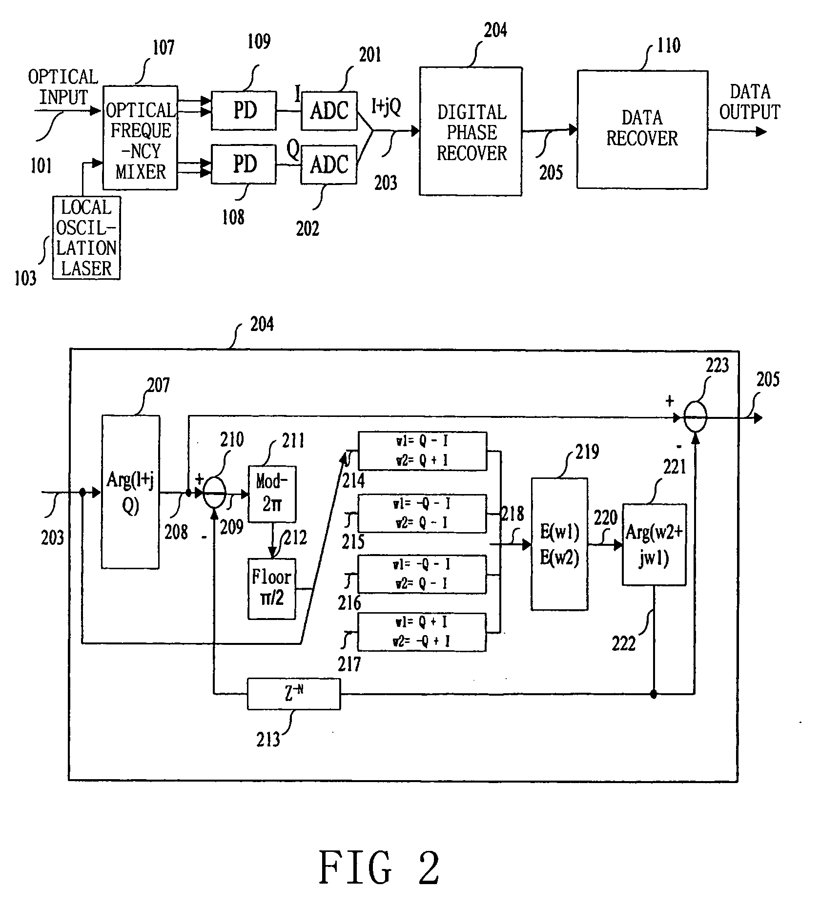
[0032]FIG. 3 shows a frequency offset compensating apparatus according to the first embodiment of the present invention. FIG. 3A illustrates serial implementation of the apparatus, and FIG. 3B illustrates parallel implementation of the apparatus. In FIG. 3A, the input 203 is a received base band digital signal; when there is frequency offset, the input 203 can be expressed as I+jQ=exp(jφd+jφ+jkΔωT), where φd is data information, φ is phase offset introduced by line width of the laser etc., Δω is frequency offset, T is symbol period, k indicates time sequence of the arriving symbols, kΔωT is phase offset introduced by the frequency offset, and j indicates an imaginary number unit. The input 303 is phase offset change (namely ΔωT) introduced by the frequency offset wi...


PUM


Abstract

The present invention relates to a frequency offset compensating apparatus and method, and an optical coherent receiver. The optical coherent receiver includes a front end processor and a frequency offset estimator, of which said front end processor converts an inputted optical signal into a base band digital electric signal, and said frequency offset estimator estimates a phase offset change introduced by a frequency offset in said base band digital electric signal; said frequency offset compensating apparatus comprises an M output integrator, for integrating the phase offset change introduced by the frequency offset to acquire M inverse numbers of the phase offset introduced by the frequency offset, where M is an integer greater than 1; a series-parallel converting device, for dividing said base band digital electric signal into M sub base band digital electric signals; M complex multipliers, for constructing the corresponding inverse numbers in the M inverse numbers to be complex numbers, and multiplying them with the corresponding sub base band digital electric signals in the M sub base band digital electric signals; and a parallel-series converting device, for converting the M sub base band digital electric signals multiplied by said complex multipliers into a base band electric signal.

Description

FIELD OF THE INVENTION[0001]The present invention relates to optical communications, and more particularly, to an optical coherent receiver.BACKGROUND OF THE RELATED ARTS[0002]With the gradual enhancement on the requirements of capacity and flexibility of the optical communication system, the coherent optical communication technology has become more and more important. In comparison with incoherent technology (such as on-off key, OOK) or self-coherent technology (such as differential quadrature phase-shift keying, DQPSK), the coherent technology has the following advantages: optical signal-to-noise ratio (OSNR) gain of approximately 3 dB; the capability to use more efficient modulation technologies (such as quadrature modulation, QAM) to enhance transmission capacity, and the capabilities to make convenient use of electric equalization technology in response to channel change, and lower production cost, etc. Coherent reception requires that the frequency and phase of the local oscil...

Claims


Application Information

Patent Timeline
IPC IPC(8): H04B10/06H04B10/2507H04B10/516H04B10/61H04L27/38
CPCH04B10/61H04B10/6165H04B10/613
Inventor LI, LEITAO, ZHENNINGNAKASHIMA, HISAO
Owner FUJITSU LTD
Why Eureka
Try Eureka