
Method and apparatus for locating faults in communications networks

Active Publication Date: 2013-07-18
KAELUS
View PDF0 Cites 78 Cited by
  • Summary
  • Abstract
  • Description
  • Claims
  • Application Information

AI Technical Summary

Benefits of technology

The patent text describes a method for improving the resolution of magnetic resonance imaging (MRI) by measuring the complex PIM values of a vector and using a window function to smooth the resulting data. This method can be used to detect and analyze peaks in the MRI data. Alternatively, a different method called the Modified Covariance Estimator can be used, which offers a slightly less precise resolution but is less prone to numerical problems. The use of these methods can improve the quality of MRI data and improve the accuracy of detecting and analyzing peaks.

Problems solved by technology

Passive intermodulation distortion (PIM) is a form of electromagnetic interference that is often encountered in radio communications systems such as cellular mobile telephone networks.
This is because in many situations the frequency of the PIM signal falls within the passband of the base station's receiver, resulting in loss of sensitivity and an increased bit error rate.
PIM faults in cell sites can be difficult and time-consuming to diagnose and repair.
However, in many (but by no means all) cell sites the only PIM products of interest are the odd-ordered products below the carrier frequencies F1 and F2, as it is these products that are usually responsible for the majority of PIM problems encountered in practice.
For example, some cellular networks are vulnerable to the odd-ordered PIM products located above the transmit band rather than below it.
Similarly, even-ordered PIM products can be problematic in certain circumstances.
Unfortunately, scalar PIM analysers as discussed in the applicant's earlier applications are only capable of measuring the overall PIM level in a cable network.
They do not provide any information about the locations of individual PIM faults.
Both of the above approaches are less than optimal.
Similarly, the second method can also be very labour-intensive and time-consuming, especially in crowded cell sites with large bundles of feeder cables strapped together on the same mast.

Method used

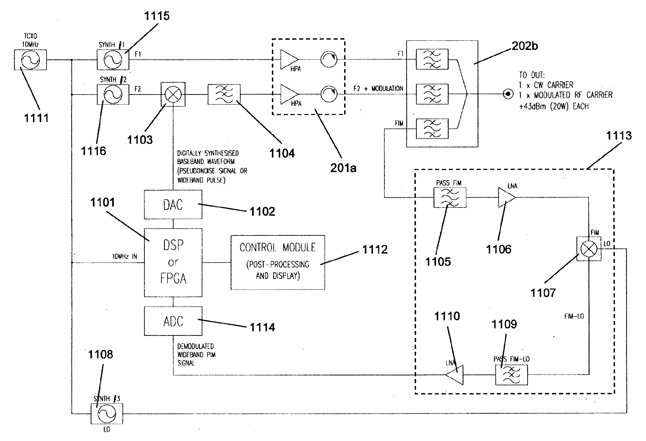
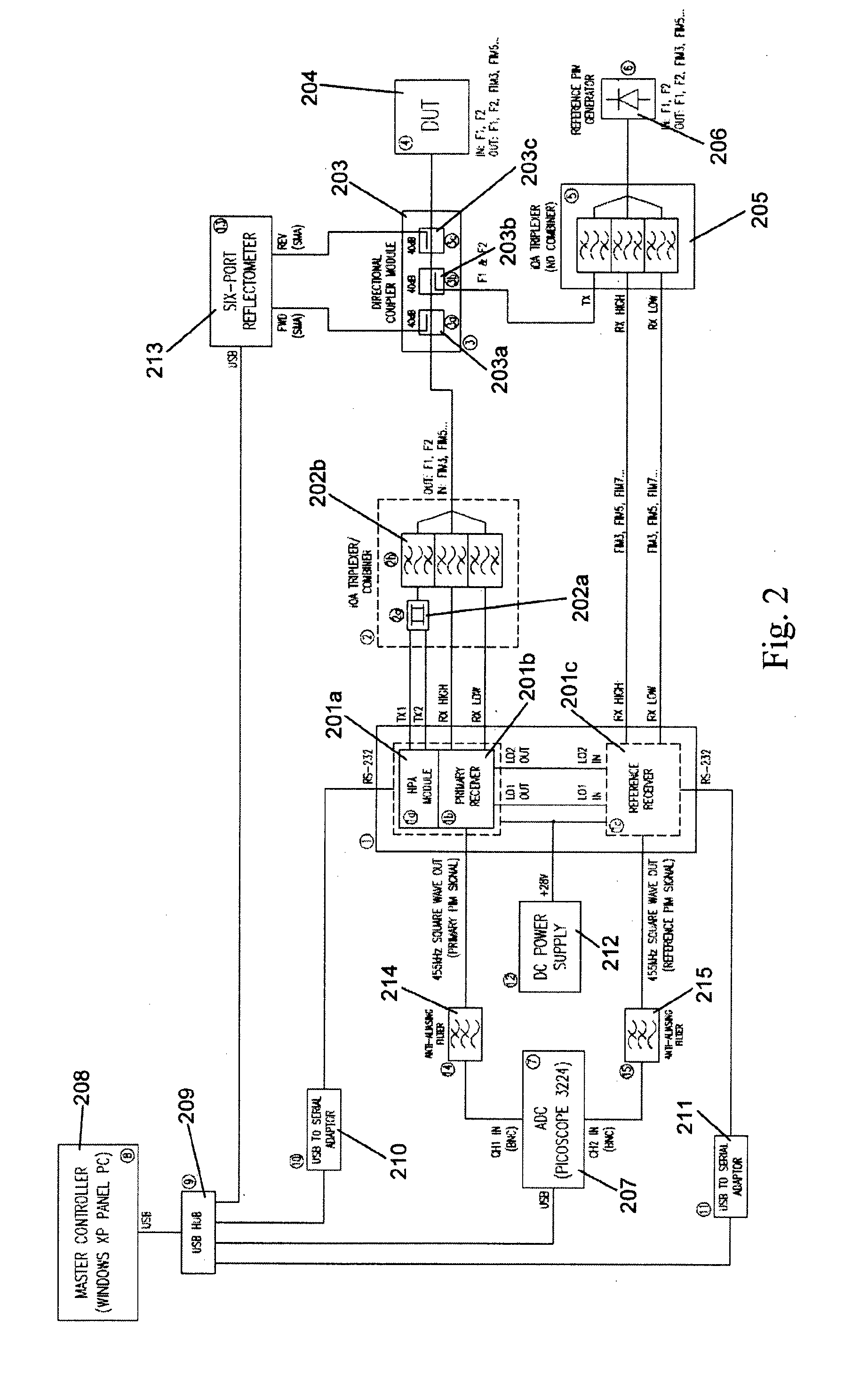

Image

  • Method and apparatus for locating faults in communications networks
  • Method and apparatus for locating faults in communications networks
  • Method and apparatus for locating faults in communications networks

Examples


Embodiment Construction

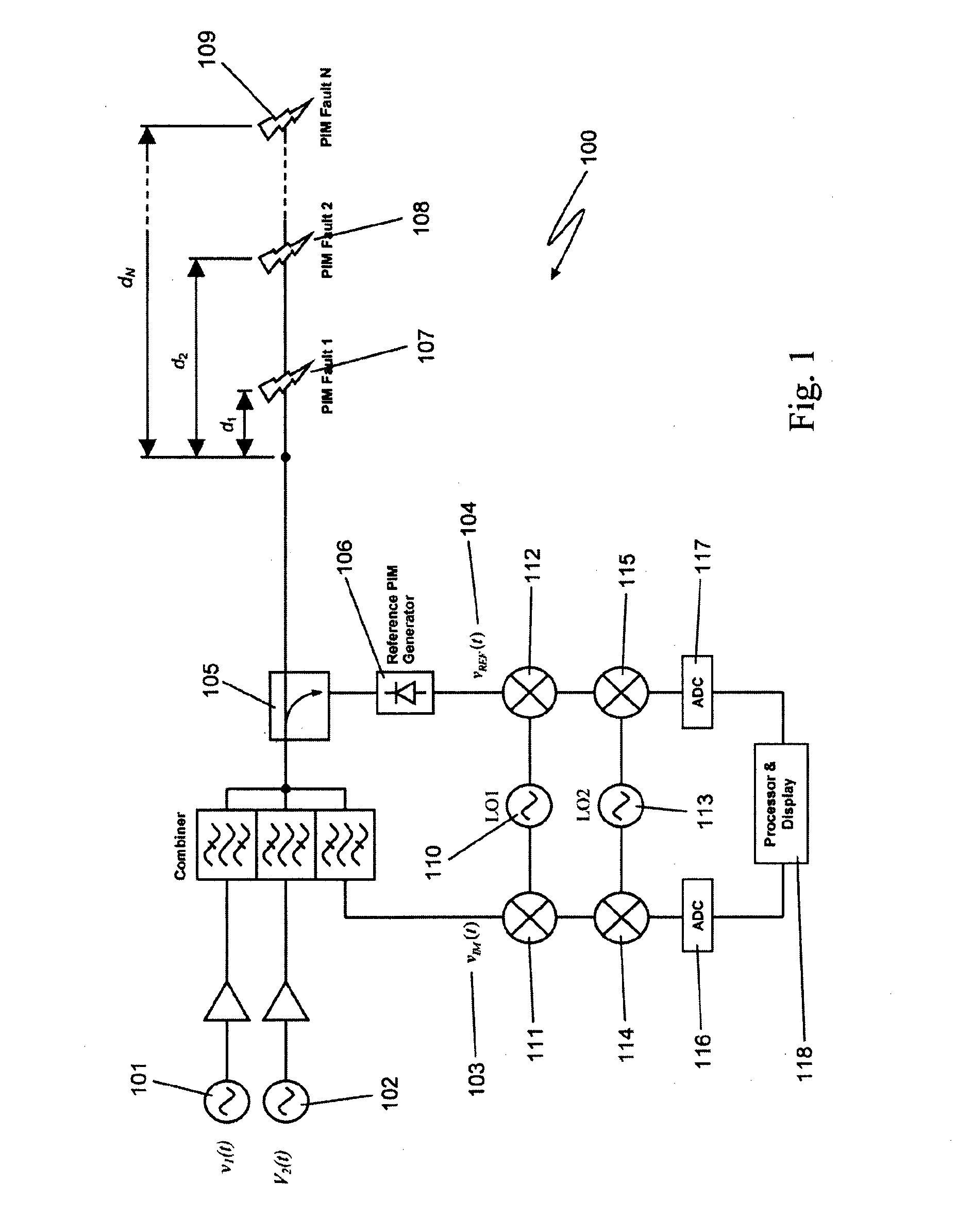
[0092]With reference to FIG. 1 there is illustrated a simplified block diagram of the test apparatus 100 according to one embodiment of the present invention. As shown a pair of high-power, frequency-synthesised, unmodulated RF carriers v1(t) 101 and v2(t) 102 are generated inside the HPA module of the apparatus. The power and frequency of v1(t) 101 and v2(t) 102 can be independently set to a range of values. v1(t), v2(t) are combined inside the instrument and then applied to the input of the device under test (DUT).

[0093]vIM(t) 103 is the primary PIM signal. It is the vector sum of all the PIM signals 107, 108, 109 generated in the DUT. It usually has a very low power level (typically much less than −80 dBm). A reference tone vREF (r) 104 is generated inside the apparatus 100. It has the same frequency as the primary PIM signal 103 and is derived by taking a sample of the two high-power carriers v1(t) 101, v2(t) 102 via a directional coupler 105 and applying them to a double balanc...


PUM


Abstract

The present invention relates to a device for the location of passive intermodulation faults in a coaxial cable network. The test apparatus (100) according to one embodiment of the present invention utilises a pair of high-power, frequency-synthesised, unmodulated RF carriers v1(t) (101) and v2(t) (102) are generated inside the HPA module of the apparatus. The power and frequency of v1(t) (101) and v2(t) (102) can be independently set to a range of values, v1(t), v2(t) are combined inside the instrument and then applied to the input of the device under test (DUT). The PIM signals (107,108,109) generated in the DUT are combined to produce the primary PIM signal vIM(t) (103). The apparatus also includes two receivers (110,111,112,113,114,115) for the detection of vIM(t) 103 and vREF(t) (104). These signals are downconverted to 455 kHz. The two 455 kHz waveforms are digitised with a dual- channel A / D converter (116,117) and the amplitude ratio and phase offset between the digitised waveforms are calculated and stored.

Description

BACKGROUND OF THE INVENTION[0001]1. Field of the Invention[0002]The present invention relates to a device for the detection of faults in a communications network. In particular although not exclusively the present invention relates to a device for the location of passive intermodulation faults in a coaxial cable network.[0003]2. Discussion of the Background Art[0004]Passive intermodulation distortion (PIM) is a form of electromagnetic interference that is often encountered in radio communications systems such as cellular mobile telephone networks. It can arise wherever there are devices or components with nonlinear transfer characteristics. Examples include oxidised metal-on-metal junctions, components containing ferrites (such as RF circulators), components with sharp metallic edges, loose connectors, and a myriad of other imperfections such as defective plating, dirt and other forms of contamination.[0005]PIM is especially prevalent in full-duplex systems, where the transmitted an...

Claims


Application Information

Patent Timeline
IPC IPC(8): H04B17/00
CPCH04B17/0085H04B17/345H04B17/005G01R23/20G01R31/08H04B17/17
Inventor DELFORCE, GREGHORSFIELD, BRENDAN
Owner KAELUS
Learn More