Liquefied natural gas system for a natural gas vehicle

a technology of natural gas and liquefied natural gas, which is applied in the direction of machines/engines, mechanical equipment, and containers. it can solve the problems of engine power reduction, vehicle inoperableness, and inconvenient discharging of gas,

Inactive Publication Date: 2013-06-11
NORTHSTAR
View PDF21 Cites 25 Cited by
  • Summary
  • Abstract
  • Description
  • Claims
  • Application Information

AI Technical Summary

Benefits of technology

[0009]It has been recognized that it would be advantageous to develop a liquefied natural gas (LNG) system or pressure building system to build pressure in an LNG tank utilizing demand from the engine to drive flow, and without relying on pumps or gravity to drive the system.

Problems solved by technology

Special vessels and systems are used to store and transfer cryogenic liquids because of the difficulty in maintaining the extremely cold temperatures.
While the vacuum provides an effective insulation, the insulation is not perfect and heat penetrates the vessel walls.
The problem with the systems that utilize tank pressure to move the fuel to the engine is that most engines require a minimum pressure of the fuel in order to be able to generate full rated power.
If the fuel is at too low a pressure, or if the pressure in the tank is reduced due to fuel being removed, then it is possible that the engine power will be reduced or the vehicle will become inoperable.
The problem in cryogenic tanks, especially small horizontal cryogenic tanks used as vehicle tanks, is that there is only a very small liquid depth available in the tank to generate liquid head to drive a pressure building circuit.
Pressure drop in the heat exchanger and piping components is large enough that the liquid head in the tank cannot overcome the resistance to flow, resulting in no flow through the pressure building circuit, and therefore no resulting pressure increase in the tank.

Method used


Image

  • Liquefied natural gas system for a natural gas vehicle
  • Liquefied natural gas system for a natural gas vehicle
  • Liquefied natural gas system for a natural gas vehicle

Examples


Embodiment Construction

)

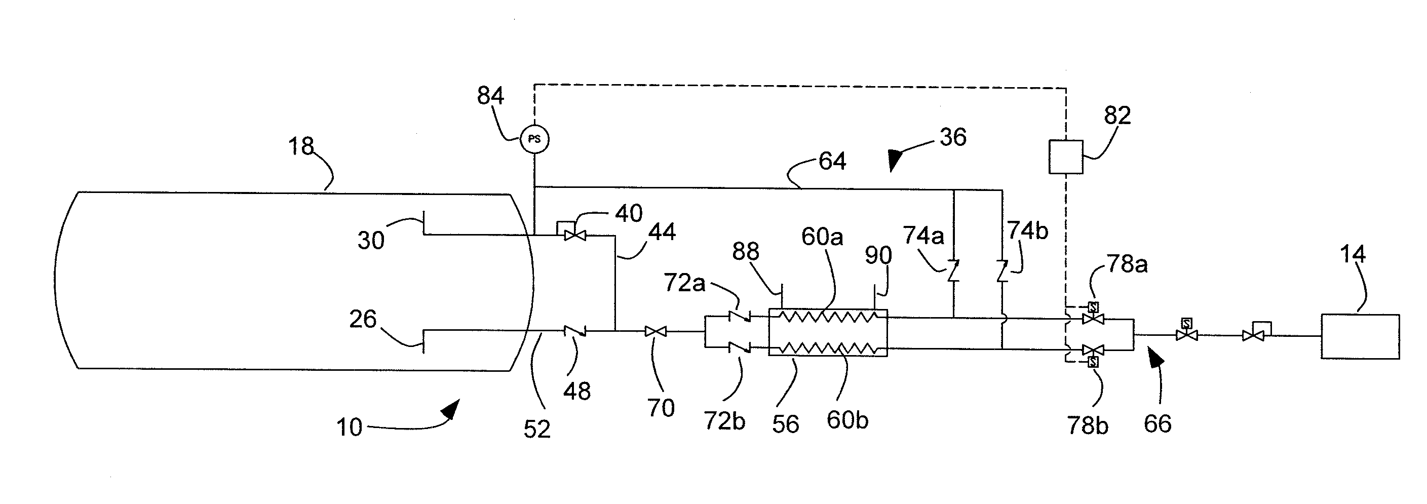
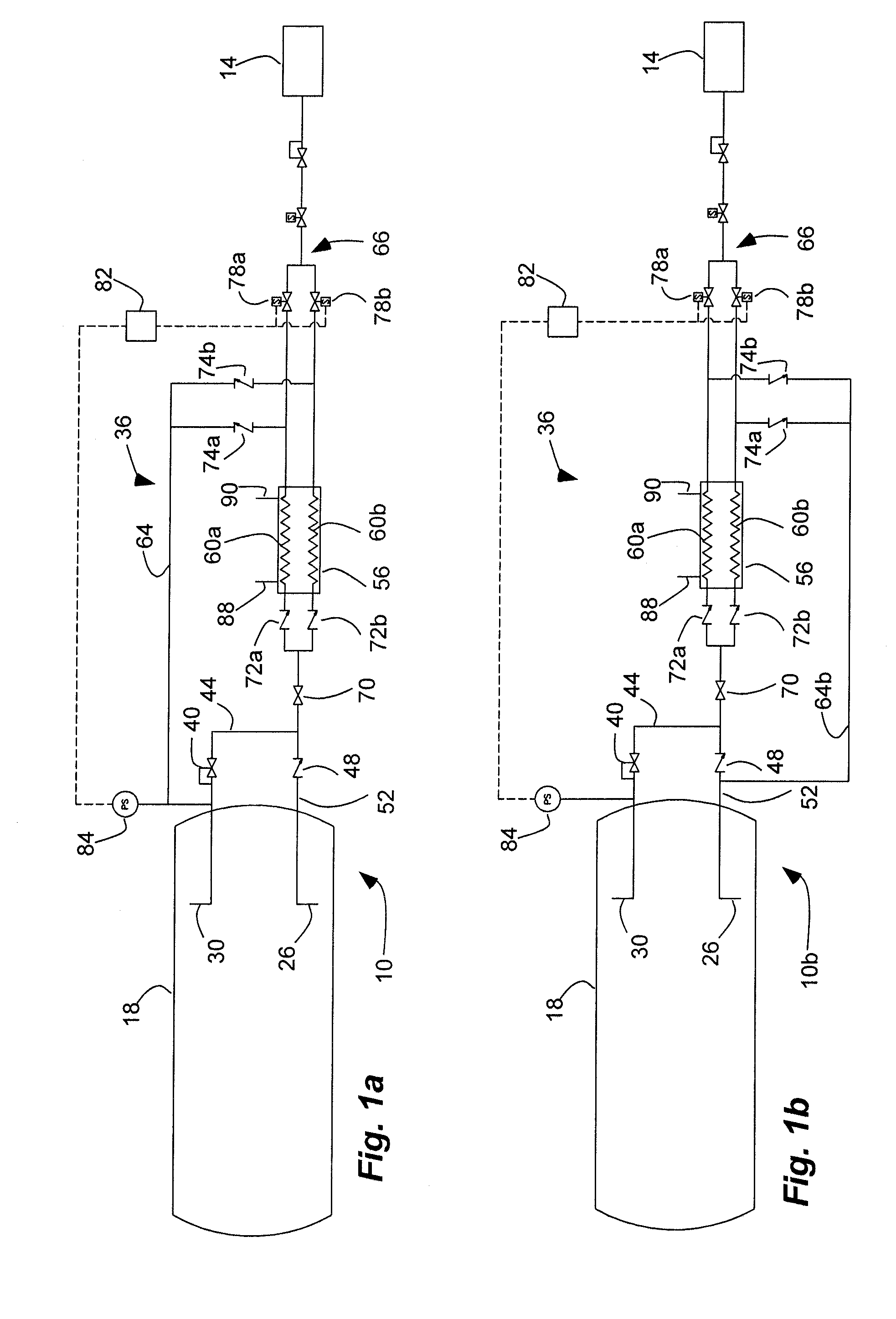
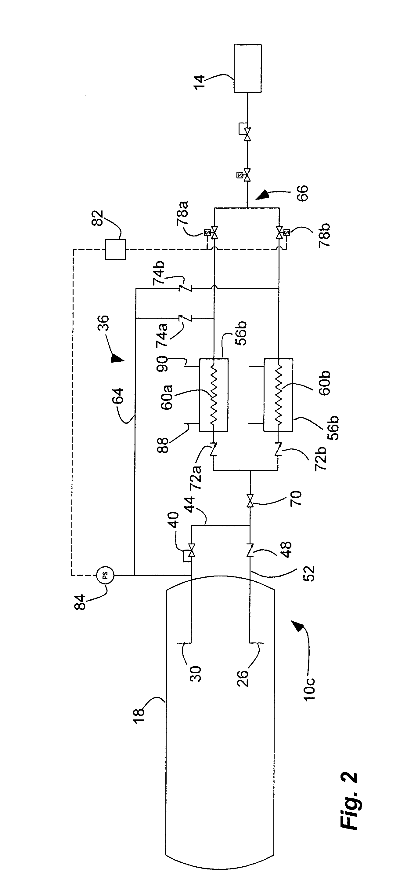
[0022]As illustrated in FIG. 1a, a liquefied natural gas (LNG) system, indicated generally at 10, is shown for a natural gas vehicle with a natural gas engine, indicated generally at 14, in an example implementation in accordance with the invention. The LNG system is a pressure building system to maintain the pressure in a vehicle fuel tank 18 at a minimum acceptable pressure so that the engine will be able to develop its full rated power. The LNG system or pressure building system described herein utilizes flow of LNG driven by demand from the engine, as opposed to systems which use a pump to move the fuel to the engine or which rely on liquid head generated by depth of liquid in the tank. The system alternates flow through dual flow paths through a heat exchanger to supply the engine, while the other path vaporizes and returns to the storage tank to pressurize the tank. The engine draws LNG from the storage tank through the dual flow paths into the heat exchanger where the LNG is...


PUM


Abstract

A liquefied natural gas system for a natural gas vehicle engine with flow driven by the engine includes dual flow paths through at least one heat exchanger. A return path extends from the dual flow paths to the storage tank, and an engine feed path extends from the dual flow paths configured to couple to the engine. A valve and control system are coupled to the dual flow paths capable of alternating flow through the dual flow paths so that one flow path supplies the engine through the engine feed path while the other flow path pressurizes the storage tank through the return path.

Description

BACKGROUND[0001]1. Field of the Invention[0002]The present invention relates generally to a liquefied natural gas (LNG) system for a natural gas vehicle engine. More particularly, the present invention relates to a liquefied natural gas system for increasing the pressure in a cryogenic fluid storage tank.[0003]2. Related Art[0004]Cryogenic liquids, such as liquefied natural gas (LNG), nitrogen, oxygen, carbon dioxide, hydrogen, and the like, are substances that normally exist as gases under normal atmospheric conditions, but are liquids at very low temperatures. Special vessels and systems are used to store and transfer cryogenic liquids because of the difficulty in maintaining the extremely cold temperatures. Such vessels typically include a double walled vessel having insulation and vacuum in the annular space. While the vacuum provides an effective insulation, the insulation is not perfect and heat penetrates the vessel walls. When heat is added to the cryogenic liquid, a portion...

Claims


Application Information

Patent Timeline
Patent Type & Authority Patents(United States)
IPC IPC(8): F02M21/02
CPCF02B43/10F02M21/06Y02T10/32F02M21/0215Y02T10/30
Inventor DIXON, DAVIDOLDHAM, MARKOLDHAM, KENNY
Owner NORTHSTAR
Why Eureka
Try Eureka