Dual-swath imaging system

a dual-swath, electrooptical imaging technology, applied in the field of photogrammetric imaging systems, can solve the problems of introducing artifices, wasting precious image resources, and the size of the ccd and cmos area arrays currently available for use in such systems, and achieves the effect of easy processing and higher pixel coun

Active Publication Date: 2013-06-11
KEYW
View PDF38 Cites 20 Cited by
  • Summary
  • Abstract
  • Description
  • Claims
  • Application Information

AI Technical Summary

Benefits of technology

[0009]It is another object of this invention to provide a highly reliable simple two camera imaging system which simultaneously captures a pair of left and right nadir shooting digital aerial photos having a strip of narrow overlapping field at the center of its composed panoramic frame or the edges of the left and right images from each camera.
[0012]It is a further object of this invention to provide a dual camera system that acquires dual-swathes of two adjacent images with a narrow overlapped vertical strip at center. This narrow center overlap consists of a stereo pair that is acquired by two simultaneously exposed cameras with a fixed length of stereo baseline (distance between two shots) and the same attitude induced by aircraft roll, pitch, and yaw dynamics. This narrow strip of overlapped images can be more easily processed by simplified photogrammetric algorithms to provide a software altimeter or range finder function for this dual-swath imaging system.
[0013]It is another object of this invention to provide a portable airborne camera system using only two 6 cm by 4.5 cm format frame transfer CCD sensors to provide industrial leading large frame size options of 78 megapixels and 120 megapixels today and even higher pixel count options in the future.
[0016]It is yet another object of this invention to provide a dual camera system that acquires quickly deliverable precisely geo-referenced nadir shooting panoramic images rather than oblique shooting fan shaped images.

Problems solved by technology

A major limitation is the size of the CCD and CMOS area arrays currently available for use in such systems.
Extra cost is associated with these extra tilted-photograph processes, including to correct the fan shaped images with variable resolution to rectangular images with data interpolation, which wastes the precious image resources, introduces artifices, and sacrifices image quality.
However, this camera system typically uses four (4) lenses and fifteen (15) 35 mm format area sensor arrays, and is a fairly complicated system.
The hardware is massive and heavy.
It is complicated to build, calibrate, operate, and maintain.
With 15 critical non-redundant sub-systems, it means a higher failure rate.
The patented processing solutions suggested many compromised options which means problematical.

Method used


Image

  • Dual-swath imaging system
  • Dual-swath imaging system
  • Dual-swath imaging system

Examples


Embodiment Construction

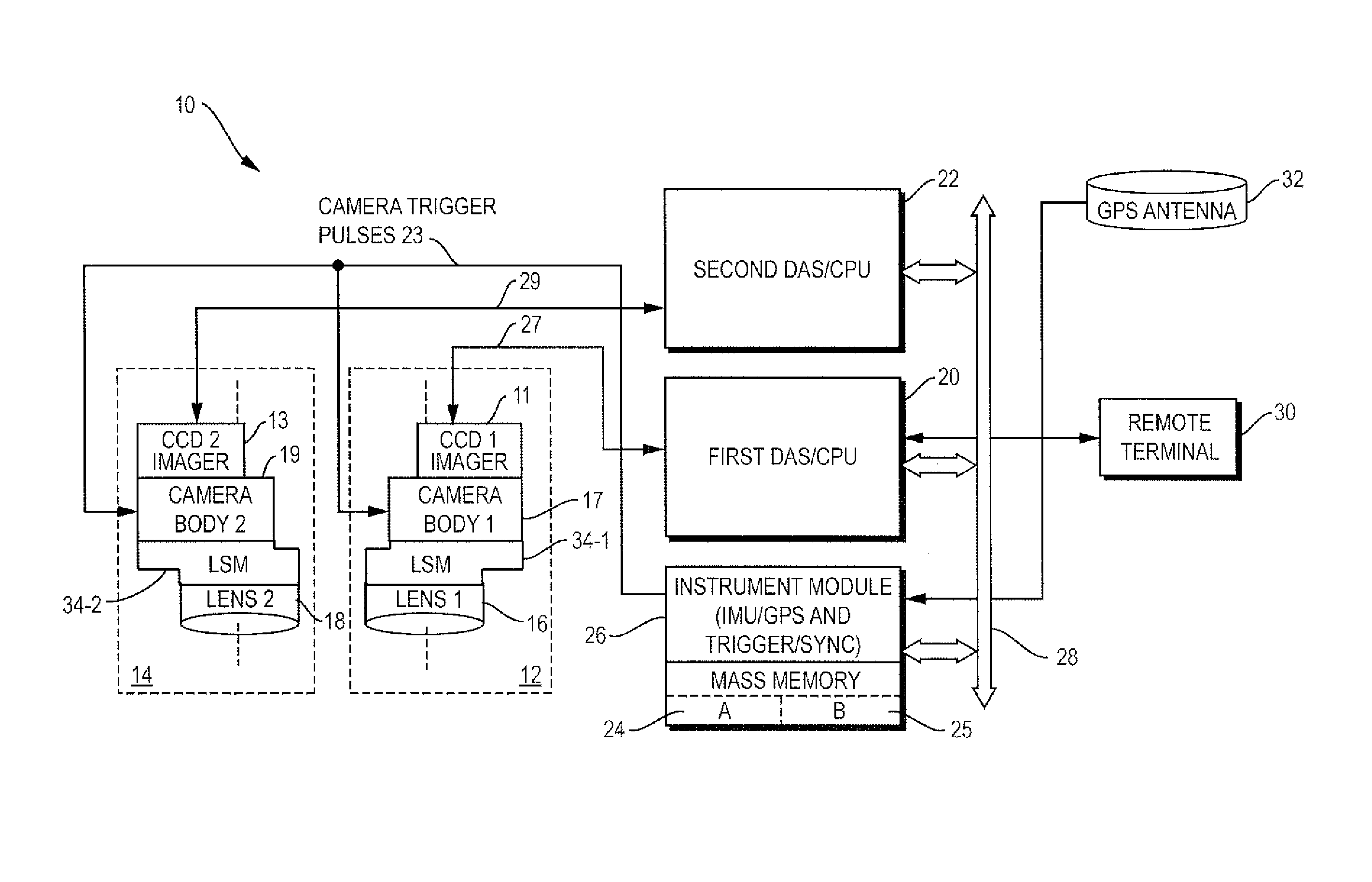
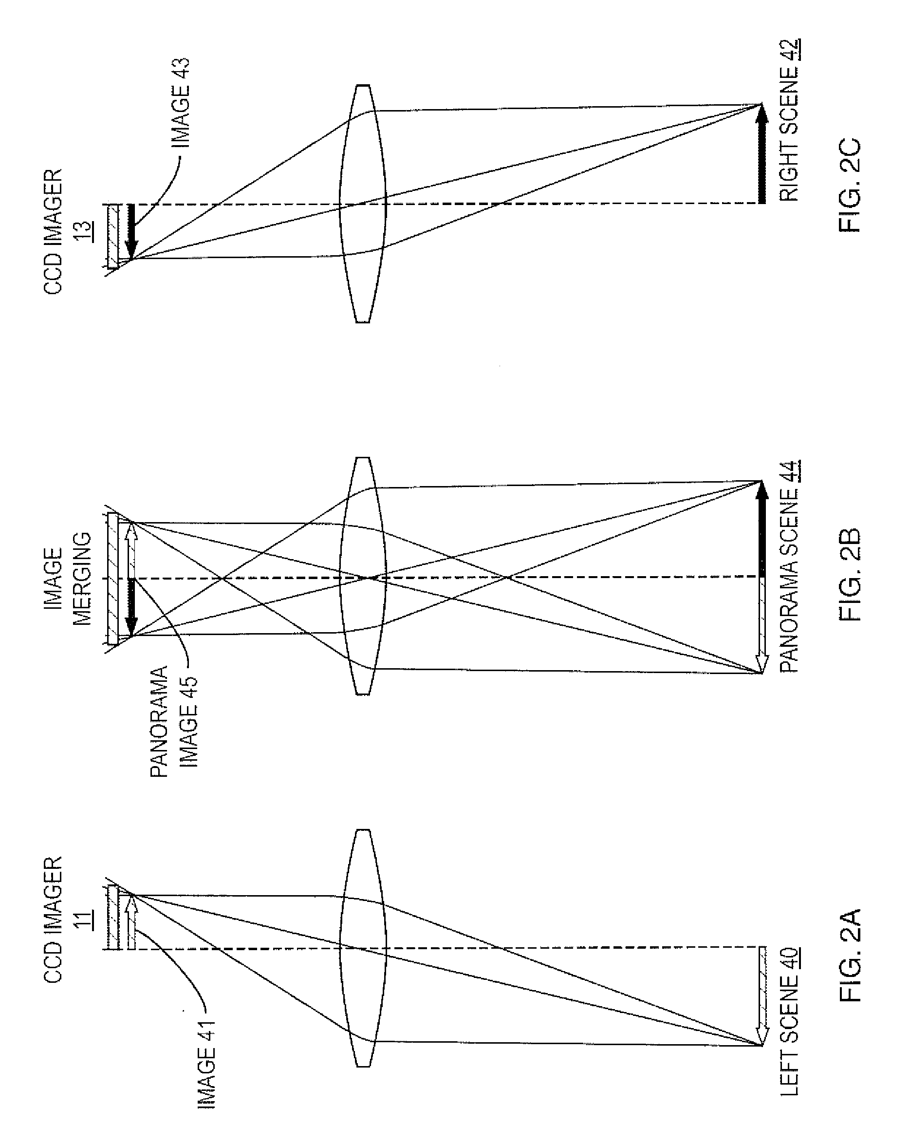
[0028]Referring to FIG. 1 a block diagram of a dual-swath electro-optical (EO) aerial imaging system 10 according to the present invention is shown comprising two cameras 12, 14 having two identical parallel mounted nadir pointing optical lenses 16, 18 with two identical CCD imagers 11, 13 mounted on a pair of specially configured camera bodies 17, 19. The camera bodies 17, 19 are attached to optical lenses 16, 18 with a pair of mechanical lens shift mounts (LSM) 34-1 and 34-2 which are mounted between camera 12 elements 16 and 17 and between camera 14 elements 18 and 19 with appropriate orientations to have the lens optical axes symmetrically shifted to left and right a predetermined distance to take dual images simultaneously (see FIGS. 2A and 2C).

[0029]Referring to FIG. 1, FIG. 6A, FIG. 6B and FIG. 6C, FIGS. 6A, 6B and 6C show the front, top and side views of a lens shift mount 34 which are used to symmetrically shift the twin lenses 16, 18 a predetermined offset to their origina...


PUM


Abstract

A portable, aerial, dual-swath photogrammetric imaging system comprising twin nadir pointing CCD cameras for simultaneously acquiring twin adjacent digital images for merging into a large panorama. A pair of lens shifters symmetrically shift twin images to the left and right sides of the focal points of two parallel lenses to extend imaging swathwidth. The twin adjacent images of the imaging system have a strip of narrow overlap at the center of the whole scene that are reserved for photogrammetric processing and stitching twin images into a seamless panorama. Each camera is connected to an embedded computer which controls imaging data acquisition, attaches GPS / IMU measurements, generates KML metadata files for its snapshots, and stores acquired images and metadata into removable SSDs. Direct geo-referenced panoramic digital stills are immediately registered on to Google™ Earth precisely. Its images can be further processed for advanced mapping, change detection and GIS applications.

Description

BACKGROUND OF THE INVENTION[0001]1. Field of the Invention[0002]This invention relates to photogrammetric imaging systems and, in particular to a dual-swath electro-optical imaging system for use in fixed wing aircrafts, helicopters, and unmanned aerial vehicles (UAV) to acquire large-format, wide-swathwidth color imagery with centimeter-level resolution.[0003]2. Description of Related Art[0004]Remote sensing applications from natural disaster response to warfighting and peace keeping operations require an advanced airborne imaging system to provide fast and large format geo-referenced and orthorectified image maps.[0005]Many airborne digital frame camera systems have come into use for mapping, reconnaissance, and surveillance applications. A major limitation is the size of the CCD and CMOS area arrays currently available for use in such systems. As a result, widespread use of digital aerial photographic systems has occurred featuring multiple arrays, multiple lenses or multiple cam...

Claims


Application Information

Patent Timeline
Patent Type & Authority Patents(United States)
IPC IPC(8): H04N7/18
CPCG01C11/025H04N5/2258H04N5/23238H04N5/3415H04N23/45H04N23/698H04N25/41
Inventor SUN, XIUHONG
Owner KEYW
Why Eureka
Try Eureka