Micro-truss based composite friction-and-wear apparatus and methods of manufacturing the same

a technology of composite friction and wear and micro-trusses, which is applied in the direction of friction lining, braking discs, braking systems, etc., can solve the problems of not providing for the creation of parts with an organized framework-like structure, affecting the performance of an automobile, and affecting the performance of the automobil

Inactive Publication Date: 2013-06-18
HRL LAB
View PDF66 Cites 17 Cited by
  • Summary
  • Abstract
  • Description
  • Claims
  • Application Information

AI Technical Summary

Problems solved by technology

In high end automotive applications, the performance of an automobile may have to be compromised to ensure that brake rotors do not fail under use, where they are subjected to extraordinary levels of wear, compressive force, and high temperatures.
The applicability of the finished part to brakes and clutches is mentioned in U.S. Pat. No. 6,086,814, but it does not provide for creation of a part with an organized framework-like structure.
However, as with the patent references described above, none of these patent publications provide for the possibility of arranging any of the ceramic, metal, or carbon components into an organized framework.
In view of the foregoing, although current high performance braking systems use a carbon / carbon, ceramic, or a carbon / ceramic composite for its rotors and / or pads, these composites do not provide for or propose making a braking system that utilizes an organized framework substructure as a component in a composite.
That is, these current composites are formed from a random network of particles or fibers dispersed throughout some matrix, and none of them utilize constructing parts wherein one of the components of the composite exists as an ordered or organized framework.

Method used


Image

  • Micro-truss based composite friction-and-wear apparatus and methods of manufacturing the same
  • Micro-truss based composite friction-and-wear apparatus and methods of manufacturing the same
  • Micro-truss based composite friction-and-wear apparatus and methods of manufacturing the same

Examples


Embodiment Construction

[0048]In the following detailed description, only certain exemplary embodiments of the present invention are shown and described, by way of illustration. As those skilled in the art would recognize, the described exemplary embodiments may be modified in various ways, all without departing from the spirit or scope of the present invention. Accordingly, the drawings and description are to be regarded as illustrative in nature, and not restrictive.

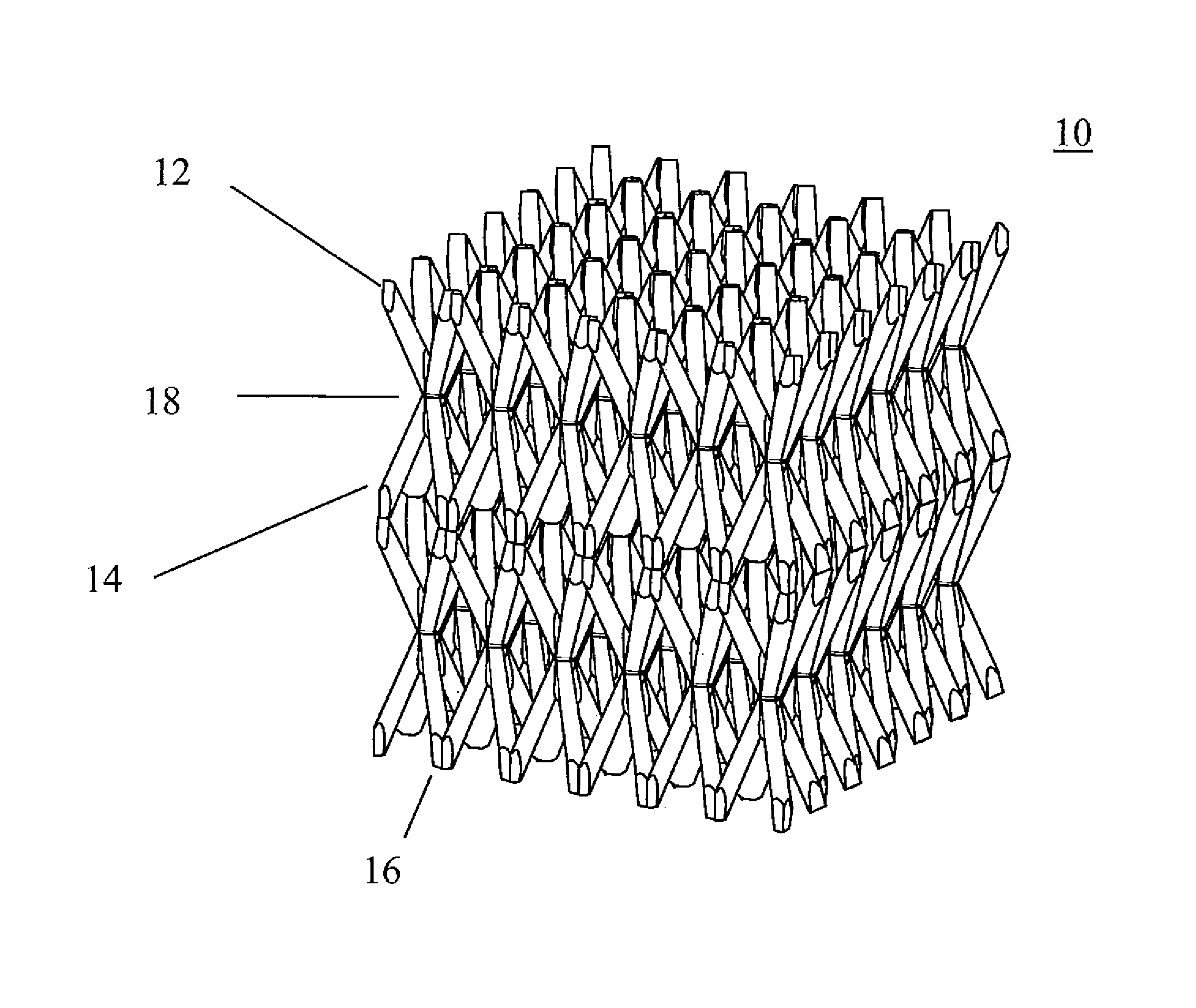
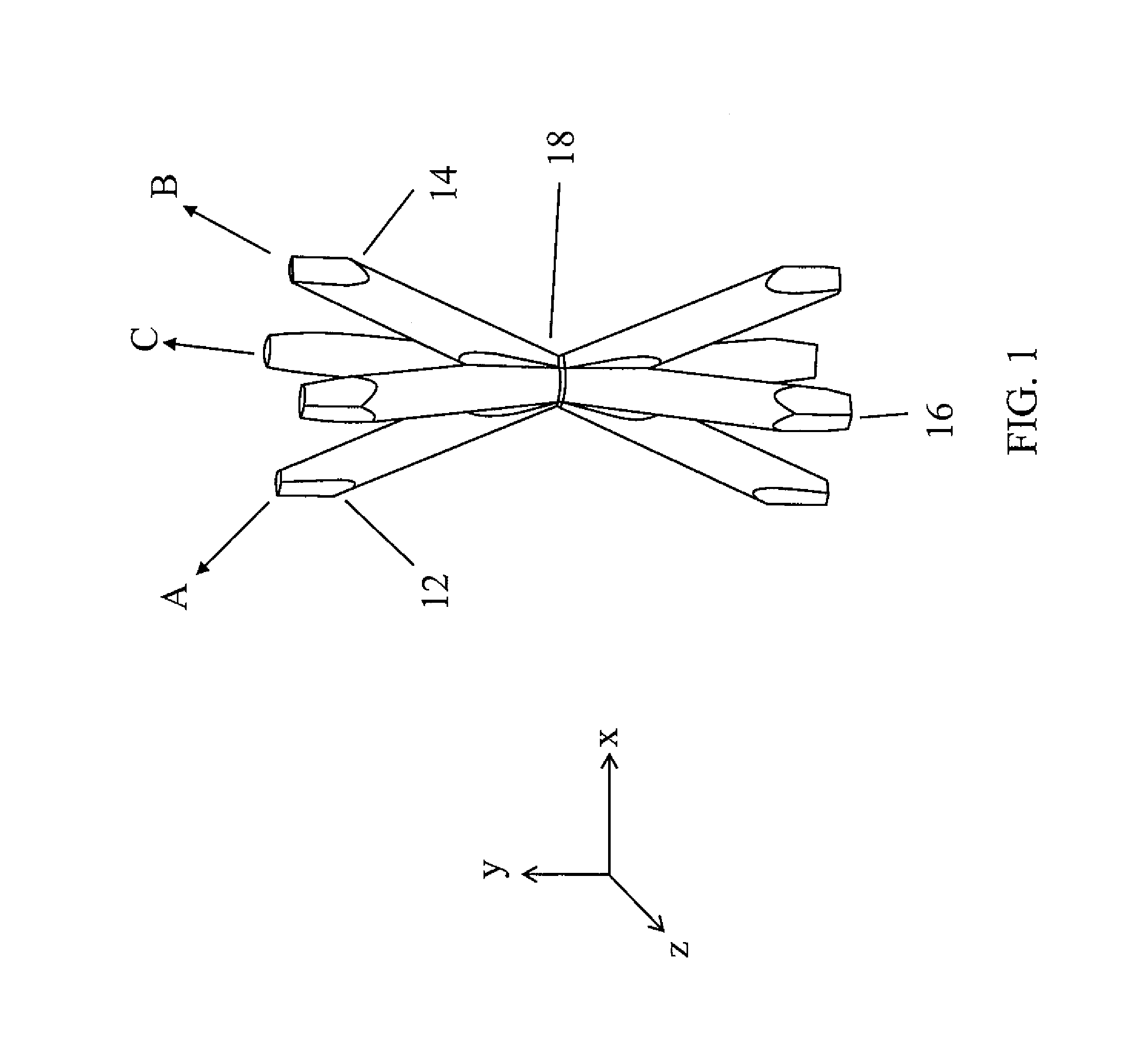
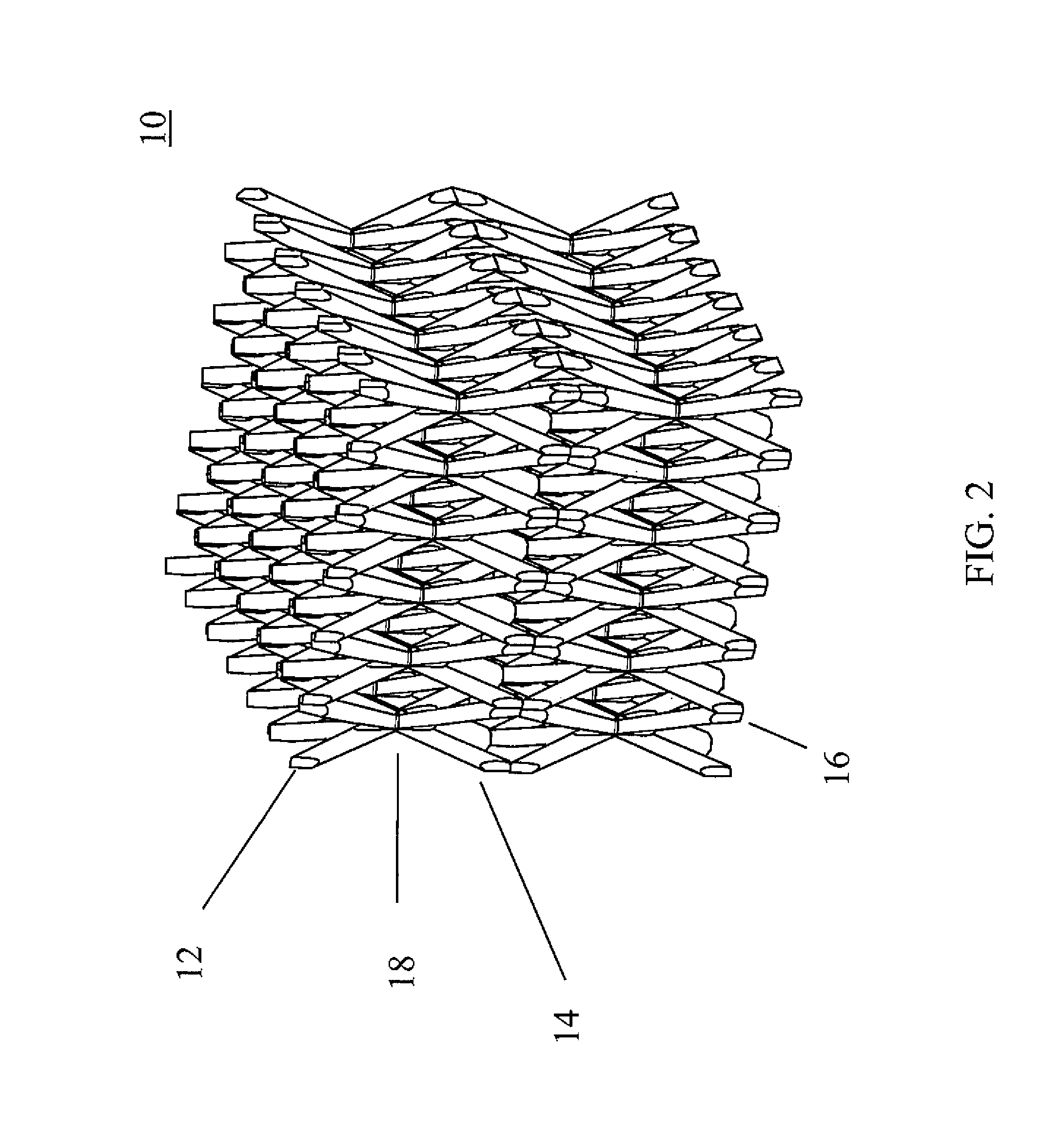
[0049]In the context of embodiments of the present invention, a three-dimensional ordered microstructure is referred to as an ordered three-dimensional structure at the micrometer scale. In one embodiment of the present invention, a micro-truss based composite friction-and-wear apparatus with a three-dimensional ordered microstructure is provided. Here, the micro-truss based composite friction-and-wear apparatus may be a micro-truss based composite clutch, brake rotor, and / or pad.

[0050]An embodiment of the present invention provides for a typ...


PUM

PropertyMeasurementUnit
diameteraaaaaaaaaa
symmetrical anglesaaaaaaaaaa

Abstract

A micro-truss based composite friction-and-wear apparatus with a three-dimensional ordered microstructure and a method creating the same. In one embodiment, the apparatus includes a filler material and a three-dimensional ordered microstructure. The three-dimensional ordered microstructure includes a plurality of first truss elements defined by a plurality of first self-propagating polymer waveguides and extending along a first direction; a plurality of second truss elements defined by a plurality of second self-propagating polymer waveguides and extending along a second direction; and a plurality of third truss elements defined by a plurality of third self-propagating polymer waveguides and extending along a third direction. The first, second, and third truss elements interpenetrate each other at a plurality of nodes to form a continuous material, the first, second, and third truss elements define an open space, the filler material occupies at least a portion of the open space, and the three-dimensional ordered microstructure is self-supporting.

Description

CROSS-REFERENCE TO RELATED APPLICATION(S)[0001]This application claims priority to and the benefit of U.S. Provisional Application No. 61 / 217,281, filed on May 29, 2009, entitled “Micro-Truss Based Composite Friction-And-Wear Apparatus And Methods Of Manufacturing The Same.” The entire contents of the above-referenced application are incorporated herein by reference.FIELD OF THE INVENTION[0002]The present invention relates to micro-truss based composite friction-and-wear apparatus and methods of manufacturing the same, and more particularly, to micro-truss based composite clutches, brake rotors, and / or pads and methods of manufacturing the same.BACKGROUND OF THE INVENTION[0003]In high end automotive applications, the performance of an automobile may have to be compromised to ensure that brake rotors do not fail under use, where they are subjected to extraordinary levels of wear, compressive force, and high temperatures. The rotors of the automobile need to be strong enough to withst...

Claims


Application Information

Patent Timeline
Patent Type & Authority Patents(United States)
IPC IPC(8): B32B3/12B32B5/14F16D65/12F16D69/00
CPCF16D65/12F16D2065/1328F16D2200/0039F16D2200/0052Y10T428/24149Y10T428/24157Y10T428/24504Y10T428/24496Y10T428/24612F16D2200/006Y10T428/249958
Inventor CUMBERLAND, ROBERT W.CARTER, WILLIAM B.JACOBSEN, ALAN J.
Owner HRL LAB
Why Eureka
Try Eureka