Dynamic light-scattering measuring apparatus using low-coherence light source and light-scattering measuring method of using the apparatus

a measuring apparatus and low-coherence light source technology, applied in the direction of measuring devices, instruments, scientific instruments, etc., can solve the problem of inability to perform single scattering measuremen

Active Publication Date: 2013-06-18
FUJIFILM CORP
View PDF11 Cites 3 Cited by
  • Summary
  • Abstract
  • Description
  • Claims
  • Application Information

AI Technical Summary

Problems solved by technology

However, depending on the particle size and a refractive index, when the particle containing solution has a high concentration to be not able to ignore an influence of multiple scattering, that is, a phenomenon that the light scattered once is scattered again by another particle, a dynamic particle characteristic that is necessary for the conventional measuring devices based on the single scattering theory differs from actual one.
Therefore, the measurement based on the single scattering cannot be performed because the phenomenon is matched with neither the theory nor the actual measurement.

Method used


Image

  • Dynamic light-scattering measuring apparatus using low-coherence light source and light-scattering measuring method of using the apparatus
  • Dynamic light-scattering measuring apparatus using low-coherence light source and light-scattering measuring method of using the apparatus
  • Dynamic light-scattering measuring apparatus using low-coherence light source and light-scattering measuring method of using the apparatus

Examples


examples

[0040]The present invention will be described in more detail based on the following examples, but the invention is not intended to be limited thereto.

[Production of Optical System]

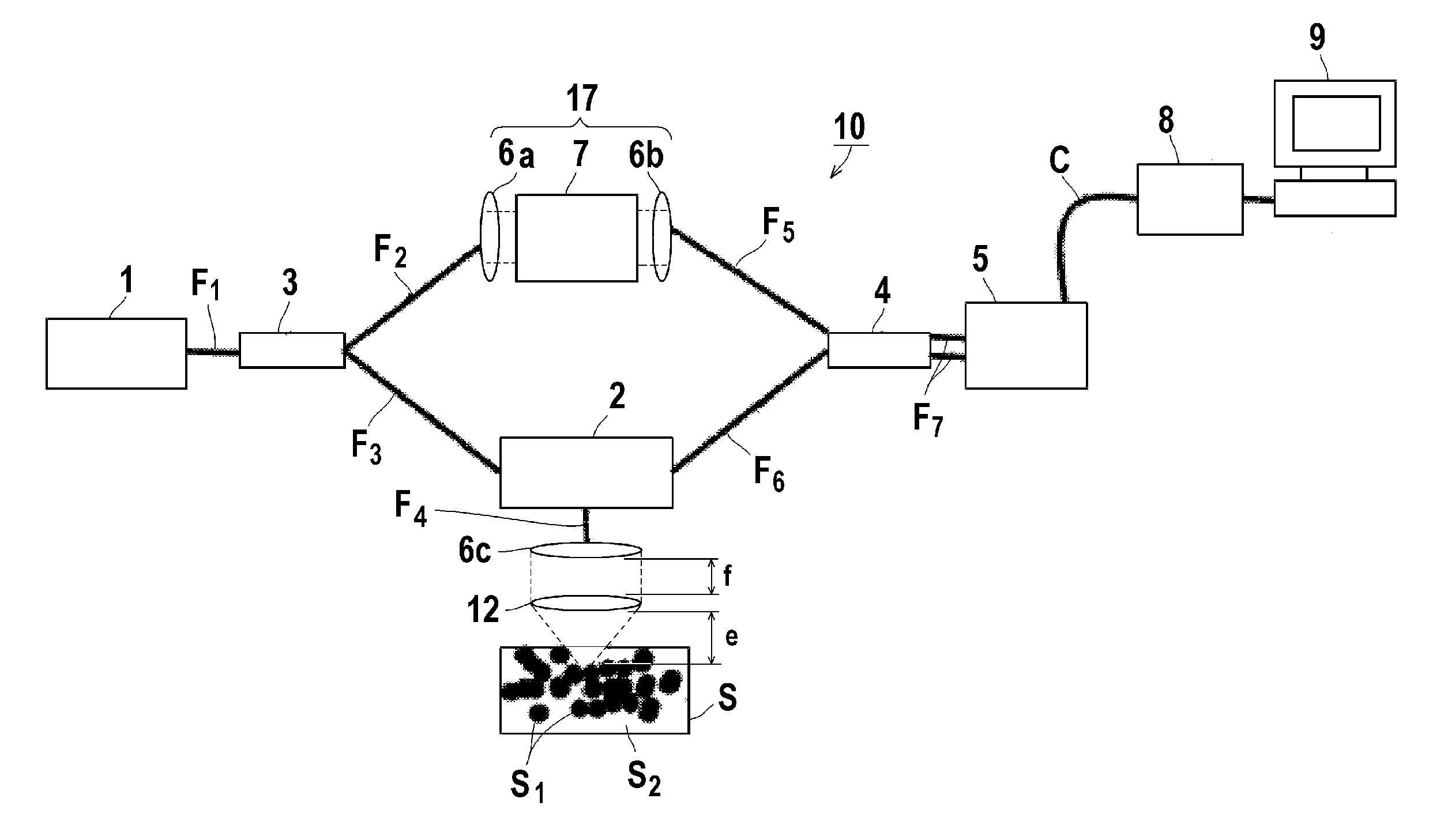
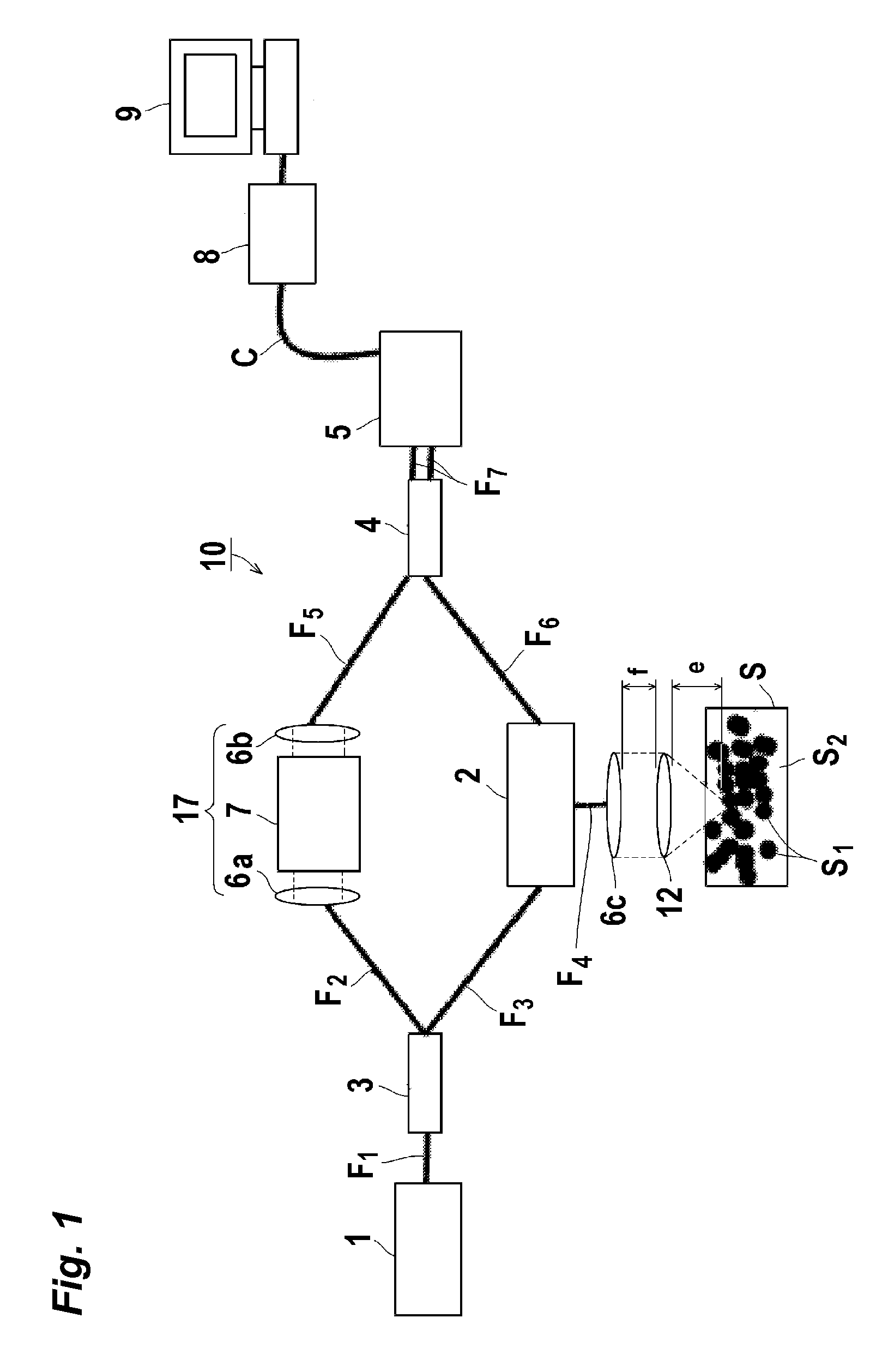
[0041]An optical system was produced based on the configuration diagram of FIG. 1. The sample S was measured while accommodated in a sample cell.

[Preparation of Polystyrene Suspension Solution]

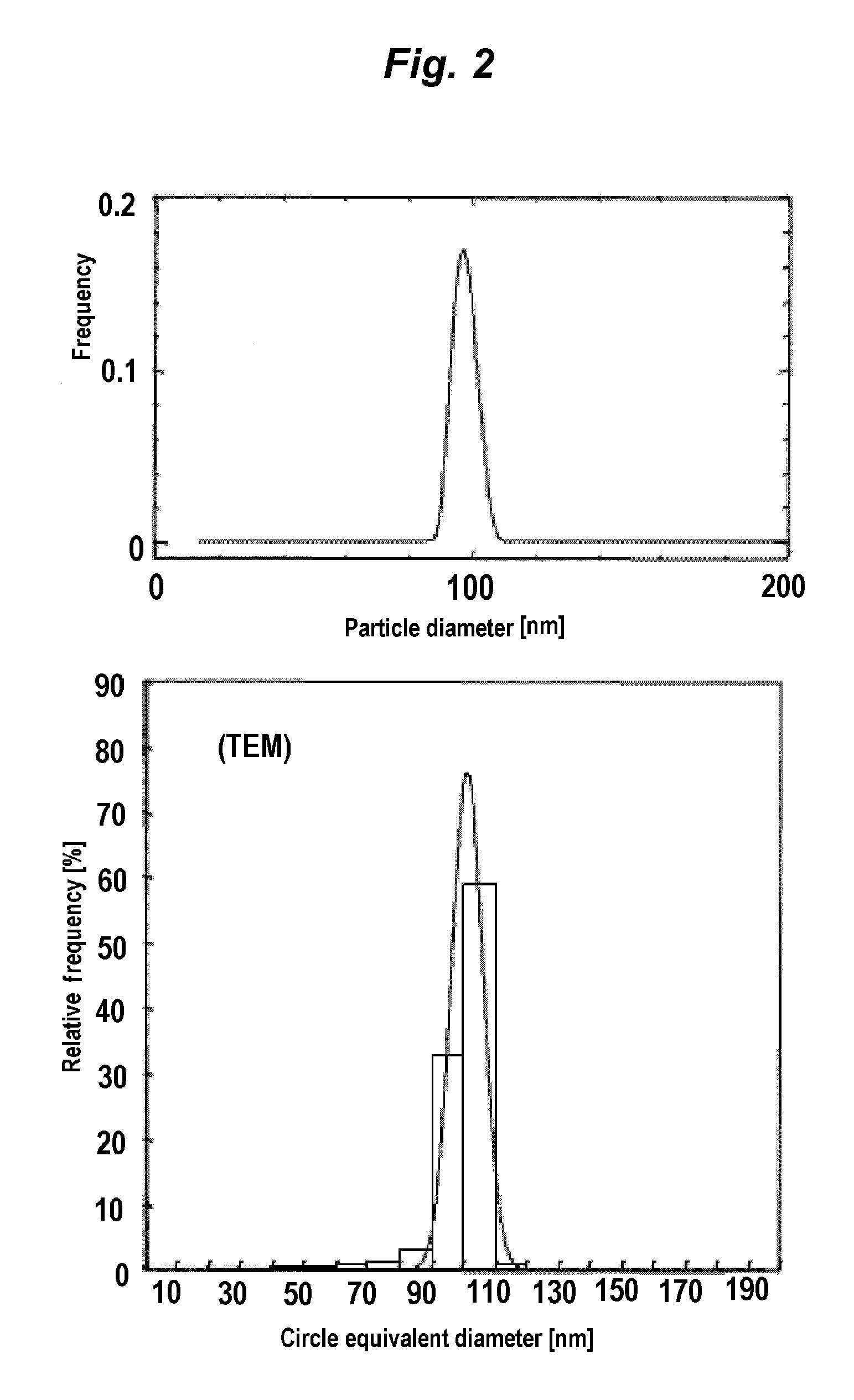
[0042]A commercially available polystyrene suspension solution was bought, and the particle size was evaluated with a transmission electron microscope. The polystyrene particles contained in a suspension solution A had a central particle size of 99 nm, and the polystyrene particles contained in a suspension solution B had a central particle size of 13 nm. A sample having a central particle size of 99 nm, a sample having a central particle size 59 nm, and a sample having a central particle size 23 nm were mixed with a mass ratio of 0.007:0.03:1, and the mixture was used as a suspension solution C prepared in a similar...

examples 1 to 3

[0043]In the polystyrene suspension A to C, the particle size was measured in the following measurement procedure with the dynamic light-scattering measuring apparatus (apparatus having the configuration of FIG. 1). The focusing position was moved to a point at a depth of about 100 mm from an interface between the sample cell and the solution, the optical path length of the scattering light or the optical path length of the reference light was adjusted such that d=dsca was obtained, and the power spectrum was measured. Then, the particle size distribution was analyzed with respect to the spectrum around modulated frequency by a CONTIN method.

[0044]FIGS. 2 to 4 and Table 1 illustrate the results. The particle size distribution measured with the transmission electron microscope is illustrated in lower-stage graphs of FIGS. 2 and 3.


PUM


Abstract

There is provided a dynamic light-scattering measuring apparatus including: a Mach-Zehnder interferometer; and a low-coherence light source. Further, there is provided a method for measuring light-scattering intensity of particles in a medium, including the steps of: providing a Mach-Zehnder interferometer; and measuring light-scattering intensity from light emitted from a low-coherence light source, in accordance with a dynamic light-scattering intensity measuring process.

Description

FIELD OF THE INVENTION[0001]The present invention relates to a dynamic light-scattering measuring apparatus using a low-coherence light source and a light-scattering measuring method.BACKGROUND OF THE INVENTION[0002]A dynamic light-scattering measuring method has already become an established technology, and a measuring device that measures a particle size of a fine particle by utilizing the method is widely used. This method has advantages including a small number of necessary parameters, nondestructive measurement, and easy-to-use handling. The dynamic light-scattering measuring method realizes the highly accurate measurement under an environment in which a single scattering theory, that is, a theory that the light scattered once is detectable without scattering another particle again can be applied in principle. For example, the particle size is accurately measured in a dilute solution containing the particle of 0.01% or less. However, depending on the particle size and a refract...

Claims


Application Information

Patent Timeline
Patent Type & Authority Patents(United States)
IPC IPC(8): G01B9/02
CPCG01J3/4412
Inventor ISHII, KATSUHIRONAKAMURA, SOHICHIROSATO, YUKI
Owner FUJIFILM CORP
Why Eureka
Try Eureka