Slotted antenna including an artificial dielectric substrate with embedded periodic conducting rings, for achieving an ideally-uniform, hemispherical radiation/reception when used as a single antenna element, or for azimuth(φ)-independent impedance-matched electronic beam scanning when used as a large antenna array

a dielectric substrate and periodic conducting ring technology, applied in the field of antennas, can solve the problems of difficult to “match” the electronic feeding circuit and the non-ideal radiation characteristics of the slot or aperture antenna for various applications, and achieve the effect of improving the radiation characteristi

Active Publication Date: 2013-06-25
POLYTECHNIC INSTITUTE OF NEW YORK UNIVERSITY
View PDF3 Cites 11 Cited by
  • Summary
  • Abstract
  • Description
  • Claims
  • Application Information

AI Technical Summary

Problems solved by technology

Slot or aperture antennas have non-ideal radiation characteristics for various applications.
This makes it practically very difficult to “match” its electronic feeding circuits in order to perform in a desired manner for scanning in all directions in θ and φ. There are simply too many directions in a 3D space for complex circuit optimizations to be implemented.

Method used


Image

  • Slotted antenna including an artificial dielectric substrate with embedded periodic conducting rings, for achieving an ideally-uniform, hemispherical radiation/reception when used as a single antenna element, or for azimuth(φ)-independent impedance-matched electronic beam scanning when used as a large antenna array
  • Slotted antenna including an artificial dielectric substrate with embedded periodic conducting rings, for achieving an ideally-uniform, hemispherical radiation/reception when used as a single antenna element, or for azimuth(φ)-independent impedance-matched electronic beam scanning when used as a large antenna array
  • Slotted antenna including an artificial dielectric substrate with embedded periodic conducting rings, for achieving an ideally-uniform, hemispherical radiation/reception when used as a single antenna element, or for azimuth(φ)-independent impedance-matched electronic beam scanning when used as a large antenna array

Examples


Embodiment Construction

[0016]The present invention may involve improved slot antennas, as well as antenna arrays including such improved slot antennas. The following description is presented to enable one skilled in the art to make and use the invention, and is provided in the context of particular applications and their requirements. Thus, the following description of embodiments consistent with the present invention provides illustration and description, but is not intended to be exhaustive or to limit the present invention to the precise form disclosed. Various modifications to the disclosed embodiments will be apparent to those skilled in the art, and the general principles set forth below may be applied to other embodiments and applications. For example, although a series of acts may be described with reference to a flow diagram, the order of acts may differ in other implementations when the performance of one act is not dependent on the completion of another act. Further, non-dependent acts may be p...


PUM


Abstract

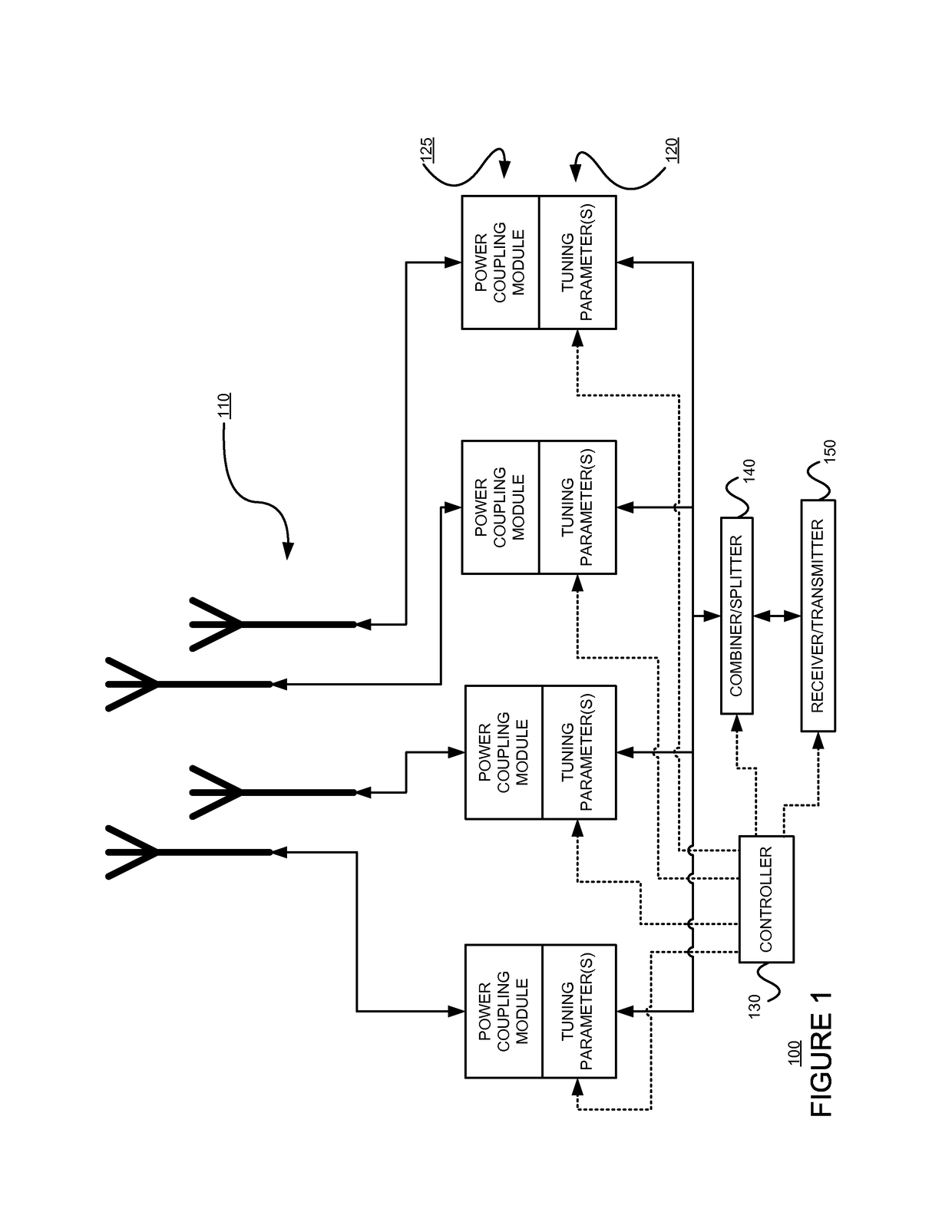
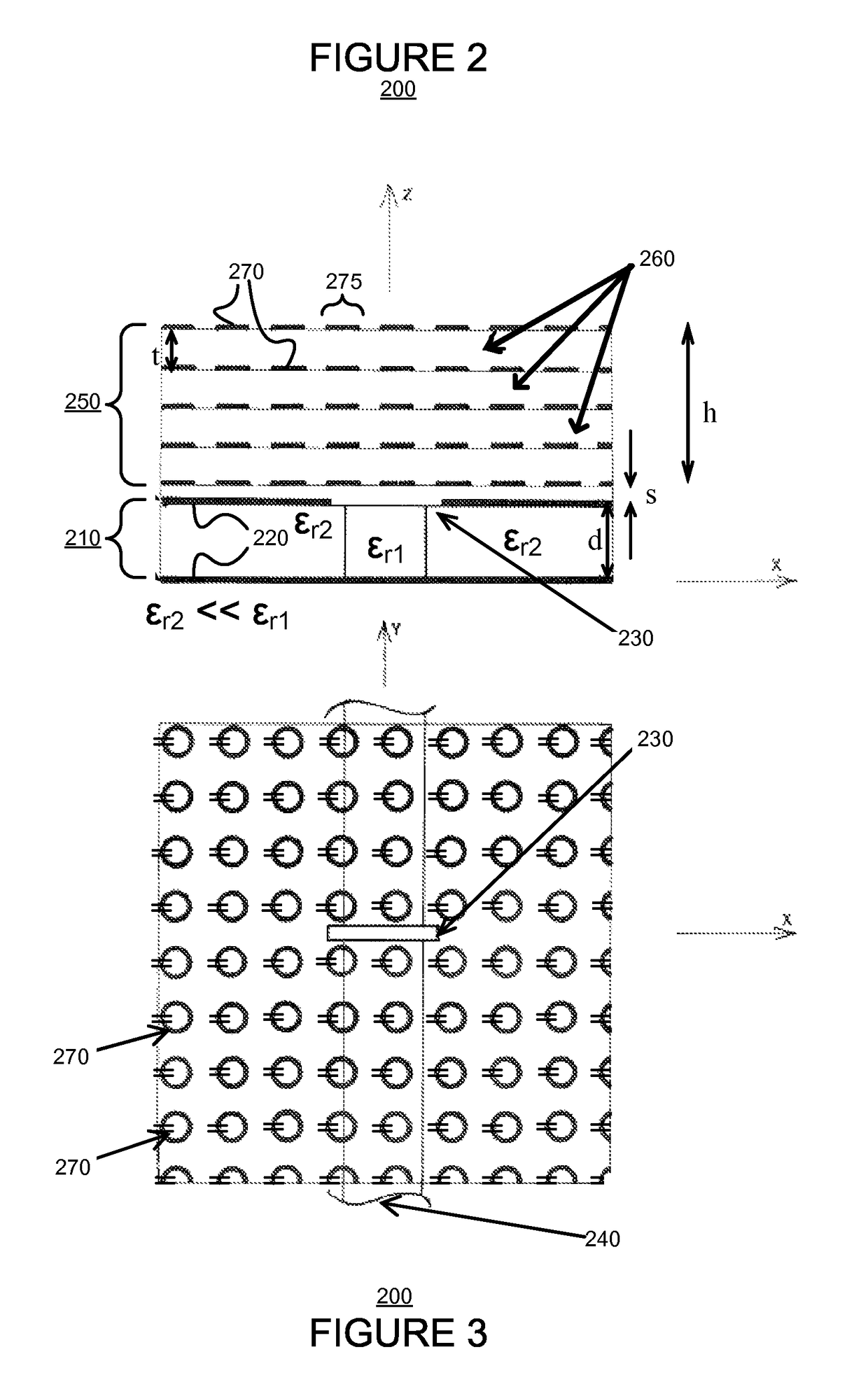
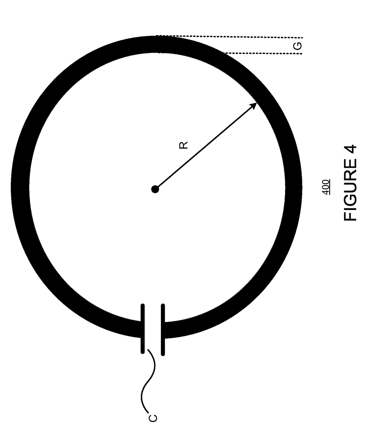
A new antenna includes a rectangular slot element provided on a conducting plate and covered by a special substrate portion. The substrate portion includes stacked layers of capacitively-loaded conducting ring elements, arranged in the form of an (e.g., periodic) array in each layer. The slot antenna element is excited by a parallel-plate waveguide, which is fabricated below the conducting plate on which the slot antenna is made. The antenna design, when used in the form of a single antenna element, would produce ideally uniform power radiation over all directions in the upper hemi-spherical space. A large periodic array of such ideally isotropic antenna elements permits electronic beam scanning and has a performance of power coupling from signal sources at the antenna inputs which is independent of the azimuth (Φ) scanning direction, dependent only on one spatial variable (elevation angle, θ) of scanning. Such performance from an antenna array normally can not be achieved using conventional designs. Such an antenna array may be used in communications and radars.

Description

§0. RELATED APPLICATIONS[0001]Benefit is claimed, under 35 U.S.C. §119(e)(1), to the filing date of U.S. provisional patent application Ser. No. 61 / 142,301 (referred to as “the '301 provisional”), titled “A NEW SLOTTED ANTENNA GEOMETRY, EMPLOYING AN ARTIFICIAL DIELECTRIC SUBSTRATE ON ITS TOP WITH EMBEDDED PERIODIC CONDUCTING RINGS, FOR ACHIEVING AN IDEALLY-UNIFORM, HEMISPHERICAL RADIATION / RECEPTION WHEN USED AS A SINGLE ANTENNA ELEMENT, OR FOR AZIMUTH(φ)-INDEPENDENT IMPEDANCE-MATCHED ELECTRONIC BEAM SCANNING WHEN USED AS A LARGE ANTENNA ARRAY,” filed on Jan. 2, 2009 and listing Nirod DAS as the inventor, for any inventions disclosed in the manner provided by 35 U.S.C. §112, ¶ 1. The '301 provisional application is expressly incorporated herein by reference. The scope of the present invention is not limited to any requirements of the specific embodiments described in the '301 provisional application.§1. BACKGROUND OF THE INVENTION[0002]§1.1 Field of the Invention[0003]The present inv...

Claims


Application Information

Patent Timeline
Patent Type & Authority Patents(United States)
IPC IPC(8): H01Q13/10H01Q15/02
CPCH01Q3/30H01Q3/34H01Q13/10H01Q21/061
Inventor DAS, NIROD K.
Owner POLYTECHNIC INSTITUTE OF NEW YORK UNIVERSITY
Why Eureka
Try Eureka