Negative electrode current collector for heterogeneous electrochemical capacitor and method of manufacture thereof

a current collector and heterogeneous electrochemical technology, applied in the direction of hybrid capacitor terminals, electrolytic capacitors, liquid electrolytic capacitors, etc., can solve the problems of limited application, increased storage energy cost, and many materials that cannot provide a wide range of capacitor operating voltages, etc., to achieve high overpotential of oxygen evolution, low specific electric resistance, and good stability

Inactive Publication Date: 2013-06-25
UNIVERSAL SUPERCAPACITORS LLC
View PDF83 Cites 1 Cited by
  • Summary
  • Abstract
  • Description
  • Claims
  • Application Information

AI Technical Summary

Benefits of technology

[0021]Many carbon materials having good stability in various electrolytes (including aqueous sulfuric acid electrolyte), low specific electric resistance, high overpotential of oxygen evolution, and low mass density, are readily available on the open market. Flexible graphite foil, which is mainly produced by the rolling of thermally expanded carbon powders, belongs to this range of carbon materials. For example, the specific electric resistance of the graphite foil known as Grafoil™ is in the range of 10−4 to 2·10−2 Ohm·cm. The content of impurities in this Grafoil™ graphite foil, the transfer of which to the electrolyte may be accompanied by a deterioration in the energy parameters of a capacitor, is rather low. Such Graphite foil has sufficient elasticity to allow for manufacture of capacitors of different configuration.
[0022]The use of flexible graphite foil to protect the basis of a capacitor current collector from mechanical damage during extended operation in a damaging electrolyte, is a novel solution aimed at increasing operational parameters of current collectors and associated electrochemical capacitors (with aqueous and non-Electrochemical aqueous electrolytes). Thus, a current collector of the present invention is capable of ensuring low and stable contact resistance with the active mass of its electrode, is preferably based on an activated carbon powder(s), may be used with asymmetric and symmetric electrochemical capacitors with aqueous and non-aqueous electrolytes, and imparts enhanced operational and cycle life parameters to its associated capacitor. The use of a current collector of the present invention in the manufacture of electrochemical capacitors designed to provide high levels of stored energy makes it possible to considerably increase the specific energy and capacity parameters of such capacitors and to enhance their sphere of application.

Problems solved by technology

Notwithstanding such a wide range of metals that may be used in current collectors, many of said materials cannot provide for a wide range of capacitor operating voltages.
As a result, capacitors employing current collectors of said materials may experience a deterioration of energy and capacity parameters, may have a greater cost of stored energy and, therefore, may be restricted in their application.
The high cost of most of the aforementioned metals is another negative aspect of the use of said metals and their alloys in the manufacture of current collectors.
This impedes development of the technology related to the manufacture of electrochemical capacitors and makes such capacitors difficult to mass produce.
A thin layer of material with high specific resistance and unstable electrical parameters will form on work surfaces of lead and lead alloy-based based current collectors after a long period of operation in an aqueous sulfuric acid electrolyte.
The use of current collectors with such a layer can cause a degradation in the energy and power parameters, stability of operation, reliability and cycle life of a capacitor.
On the one hand, it can be understood that it would be difficult to develop a universal protective coating with parameters appropriate to every capacitor.
This brings about a considerable increase in the cost of an associated current collector, and of the capacitor as a whole.
Further, many known protective coatings simply cannot impart a long service life and stable of energy and power parameters to most capacitors and, particularly, to capacitors having aqueous electrolytes.
The contact of the electrolyte with the steel basis of the current collector will, undoubtedly, bring about dissolution and breakup thereof.
During this dissolution and breakup, the transfer to the electrolyte of iron ions and other components of which the steel basis is composed will cause a dramatic increase in the self-discharge current of the capacitor to which the current collector is installed, as well as a decrease in the energy parameters of the capacitor and an accelerated failure thereof.
Other obvious drawbacks of this known current collector include the fact that the graphite foil of the protective coating has a small electric capacity and, when electrolyte gets into its pores, the foil starts to partially perform as an active material in the charge / discharge process of the capacitor.
Over a long period of operation, this process brings about swelling, deterioration of mechanical parameters, and a partial or total breakup of the graphite foil structure.
The particular design of the current collector itself is another drawback of this known current collector.
Consequently, this known current collector is not amenable to use in a capacitor with a different number of positive and / or negative electrode plates connected in parallel.
Therefore, this current collector cannot be used to create capacitors of high electric capacity and acceptable energy and power parameters.
Therefore, it can be understood that such an electrochemical capacitor employing this known current collector would have a low specific energy, low reliability, unstable energy parameters, a high energy storage cost, and a short service life.
The low specific parameters of such a capacitor would significantly limit the scope of its application.

Method used


Image

  • Negative electrode current collector for heterogeneous electrochemical capacitor and method of manufacture thereof
  • Negative electrode current collector for heterogeneous electrochemical capacitor and method of manufacture thereof
  • Negative electrode current collector for heterogeneous electrochemical capacitor and method of manufacture thereof

Examples


specific examples

Example 1

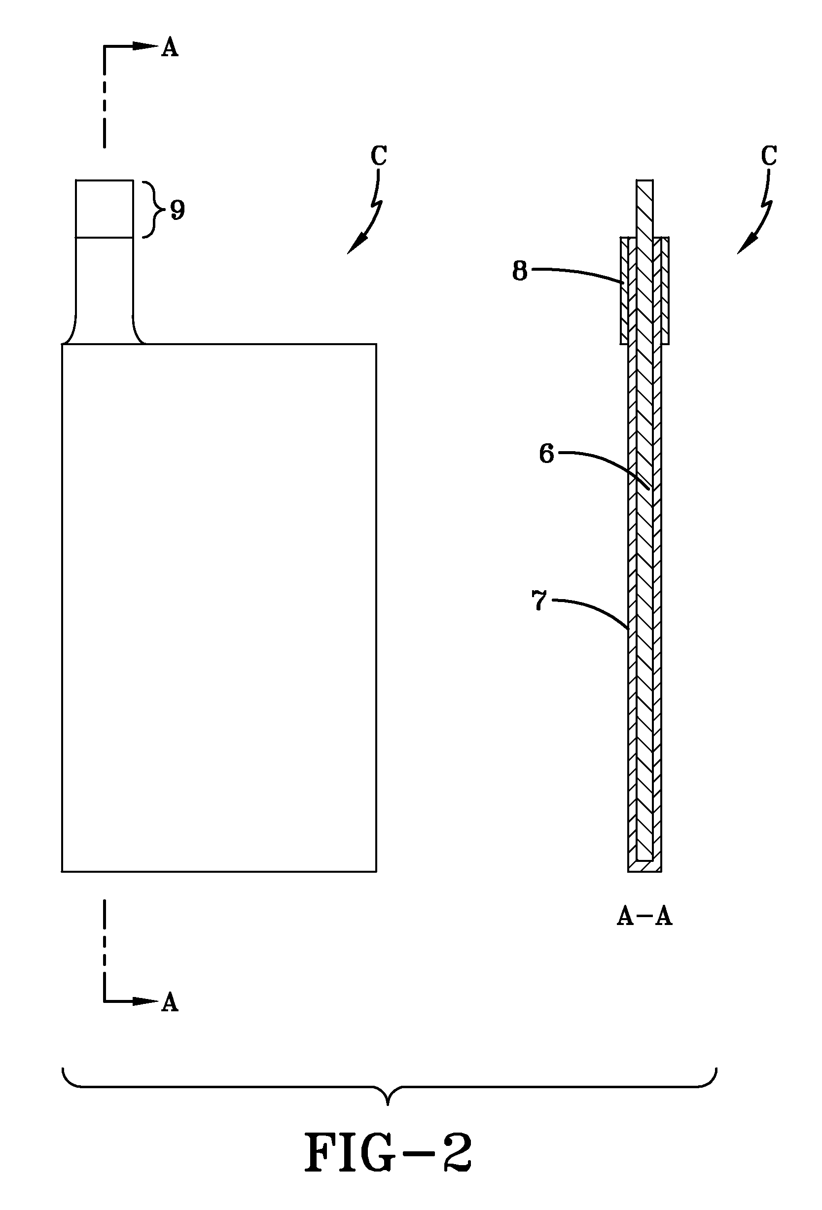
[0067]Current collector bases were cut from graphite foil having a thickness of approximately 230 μm. The overall dimensions of the current collector bases was 135 mm×72 mm×0.26 mm, as is shown in FIG. 2. The graphite foil had a specific electric resistance of 6.10−4 Ohm·cm and p-type conductivity. The mass density of the graphite foil was 1.27 g / cm3.

[0068]A protective film paste for coating the graphite foil current collector bases was manufactured using industrial carbon powder (P267E), polymer-perchlorovinyl (PVC), plasticizer (dibutyl sebacate), solvent (acetone, 11-butyl acetate and toluene), dispersant (Texaphor P61), and wetting agent (surfactant). The ratio of ingredients was 5 parts carbon powder, 15 parts PVC, 1.55 parts plasticizer, 78 parts solvent, 0.3 parts dispersant and 0.15 parts wetting agent. Following preparation and filtration, the PVC paste had a viscosity of about 775 cP (according to a Brookfield RVDV-III viscosimeter). Examination of the mass conten...

example 2

[0104]In this exemplary construction, chlorosulphated polyethylene (Hypalon®) polymer was used to protect graphite foil current collectors. In comparison to the PVC polymer used in the first capacitor HES#1, Hypalon® polymer has higher elasticity and adhesion to, among other things, carbon materials. Further, the use of this polymer in the manufacture of the protective film eliminates the need for additional components such as plasticizers and surfactants—which reduces the cost of manufacture of a current collector of the present invention.

[0105]A protective film paste was manufactured in a manner similar to that described above, and included industrial carbon powder (P267E), chlorosulphated polyethylene (Hypalon®) polymer, solvent (toluene), and dispersant (Texaphor P61). The components were present in a ratio of 2.5:8:89.45:0.05, respectively. After preparation and filtration, the Hypalon® paste had a viscosity of about 1,580 cP (according to a Brookfield RVDV-III viscosimeter). A...

example 3

[0124]Due to the fact that fluoroplastic material has an extremely high chemical stability and stable parameters in different electrolytes (including aqueous sulfuric acid electrolyte), LF-32LN varnish based on soluble fluoroplastic was used to protect graphite foil current collectors in another exemplary embodiment of the present invention. The mass composition of the LF-32LN fluoroplastic varnish was 12% fluoroplastic and 88% solvent. The viscosity of LF-32LN varnish was 68 cP (according to a Brookfield RVDV-III viscosimeter).

[0125]A protective film paste was again manufactured as earlier described. The mass composition of the paste was 3.5% industrial carbon powder (P267E), 96.35% LF-32LN varnish, and 0.15% dispersant (Texaphor P61). After preparation and filtration, the paste had a viscosity of 95 cP (according to a Brookfield RVDV-III viscosimeter). Measurements of the specific resistance and type of conductivity of an approximately 12 μm thick reference film (without a substra...


PUM

PropertyMeasurementUnit
thicknessaaaaaaaaaa
thicknessaaaaaaaaaa
particle sizeaaaaaaaaaa

Abstract

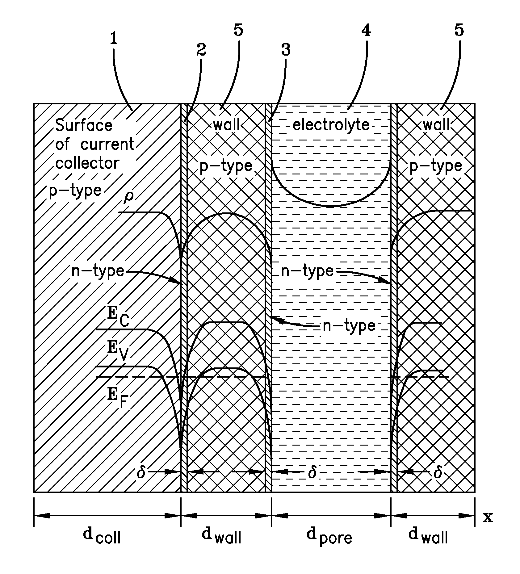
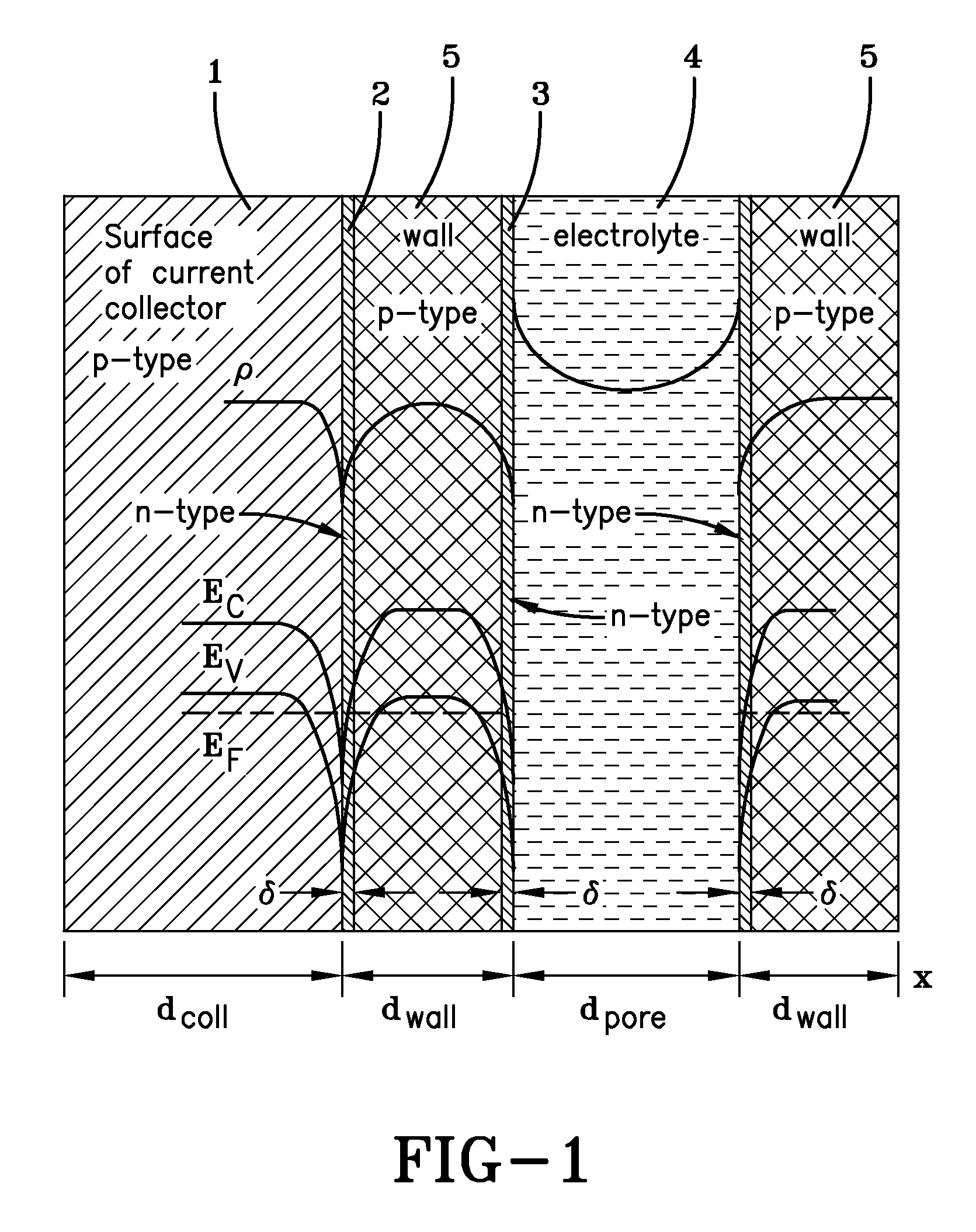
A current collector for use in an electric double layer electrochemical capacitor having a sulfuric acid electrolyte. The current collector uses a conducting carbon (e.g., graphite foil) basis with p-type conductivity. A protective film covers at least a portion of the graphite foil basis. The protective film is comprised of a conducting composite material made with a conducting carbon and a conducting organic polymer with p-type conductivity. The protective film is grown on the current collector basis such that it preferably fills the pores of the current collector basis. A lug portion of the current collector basis may be protected with an insulating polymer material.

Description

[0001]This application claims the benefit of U.S. Provisional Application No. 60 / 890,581, filed on Feb. 19, 2007 which is expressly incorporated by reference in its entirety herein.BACKGROUND OF THE INVENTION[0002]The present invention is directed to the technology and manufacture of current collectors for electrochemical capacitors and, more particularly, electric double layer (EDL) capacitors. A current collector of the present invention can be used to manufacture electrochemical capacitors having high specific energies and stable energy characteristics.[0003]Electrochemical capacitor current collectors (hereinafter current collectors) have generally been constructed of metals and metal alloys that are stable in specific aqueous and non-aqueous electrolytes. Such metals may include, for example, Al, Ti, Ni, Ag, Nb, Ta, W, Pb and Cu. Notwithstanding such a wide range of metals that may be used in current collectors, many of said materials cannot provide for a wide range of capacito...

Claims


Application Information

Patent Timeline
Patent Type & Authority Patents(United States)
IPC IPC(8): H01G9/00
CPCH01G9/016H01G9/058H01G9/155H01G11/68H01G11/70H01G11/84H01G11/58Y02E60/13
Inventor KAZARYAN, SAMVEL AVAKOVICHKHARISOV, GAMIR GALIEVICHKAZAROV, VLADIMIR ALEXANDROVICHRAZUMOV, SERGEY NIKOLAEVICHLITVINENKO, SERGEY VITALIEVICH
Owner UNIVERSAL SUPERCAPACITORS LLC
Why Eureka
Try Eureka