
Receptacle assembly

Active Publication Date: 2013-07-02
TYCO ELECTRONICS LOGISTICS AG (CH)
View PDF8 Cites 34 Cited by
  • Summary
  • Abstract
  • Description
  • Claims
  • Application Information

AI Technical Summary

Benefits of technology

This patent describes a receptacle assembly for connecting electronic components. The assembly includes a front housing with contact channels and pockets, and a restraining member with embossments that align with slots in the housing to control the position of the contact modules. The assembly also includes a plurality of contact modules with holders and a dielectric frame for electrical shielding, and the contacts have mating portions that align with the contact channels during loading. The technical effect of this design is to ensure reliable and precise connections between the electronic components.

Problems solved by technology

Signal loss and / or signal degradation is a problem in known electrical systems.
Moreover, as speed and performance demands increase, known electrical connectors are proving to be insufficient.
Such increase in density and / or reduction in size causes further strains on performance.
Due to the large number of contacts of the electrical connectors, loading the contact modules into the housing is difficult.
For example, aligning the tips of the contacts with openings through the housing is difficult.
Misalignment causes damage to the ends of the contacts.
Misalignment may also cause damage to the contacts of the mating electrical connector or may cause the electrical connectors to fail when the contacts cannot be mated.

Method used


Image

  • Receptacle assembly
  • Receptacle assembly
  • Receptacle assembly

Examples


Embodiment Construction

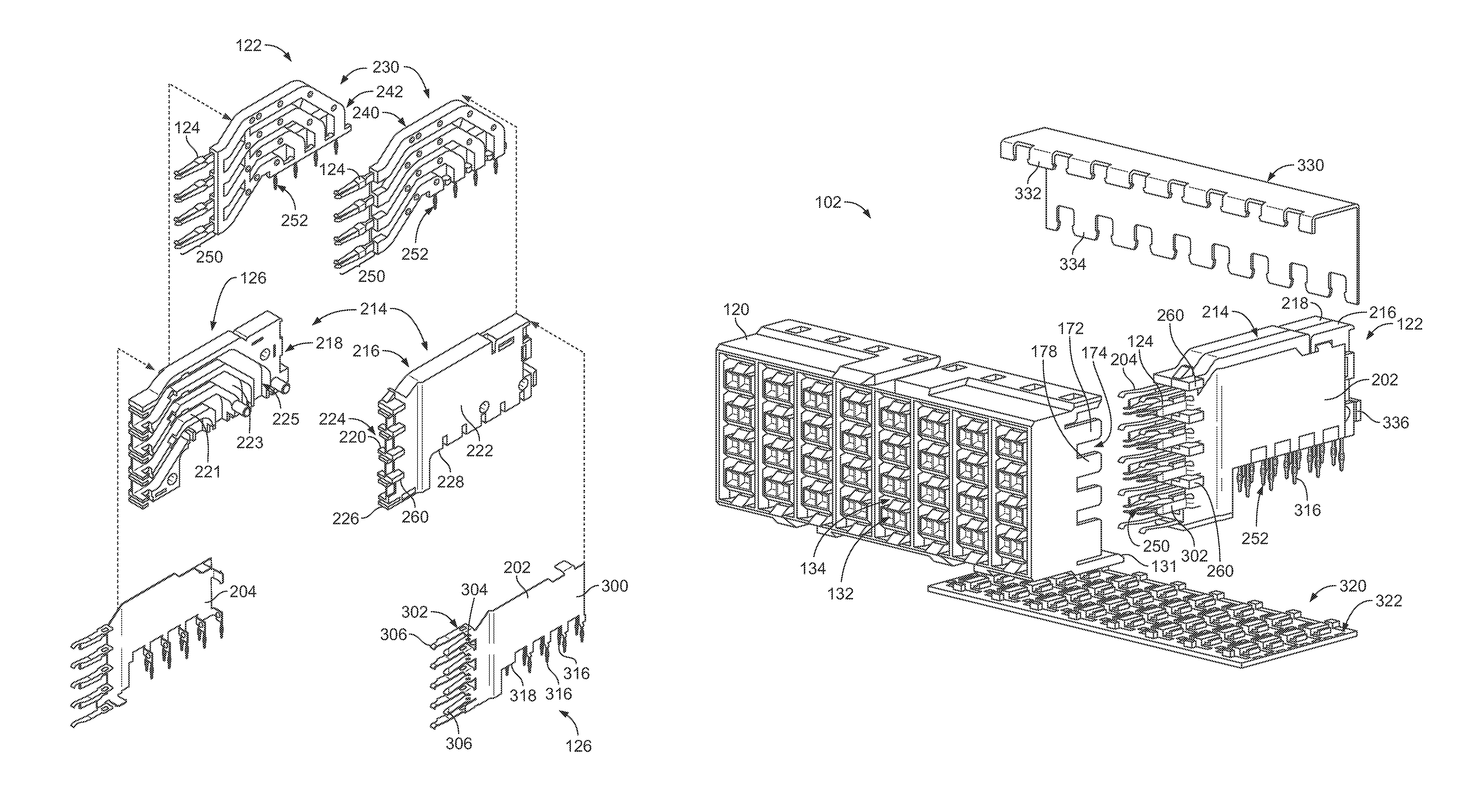
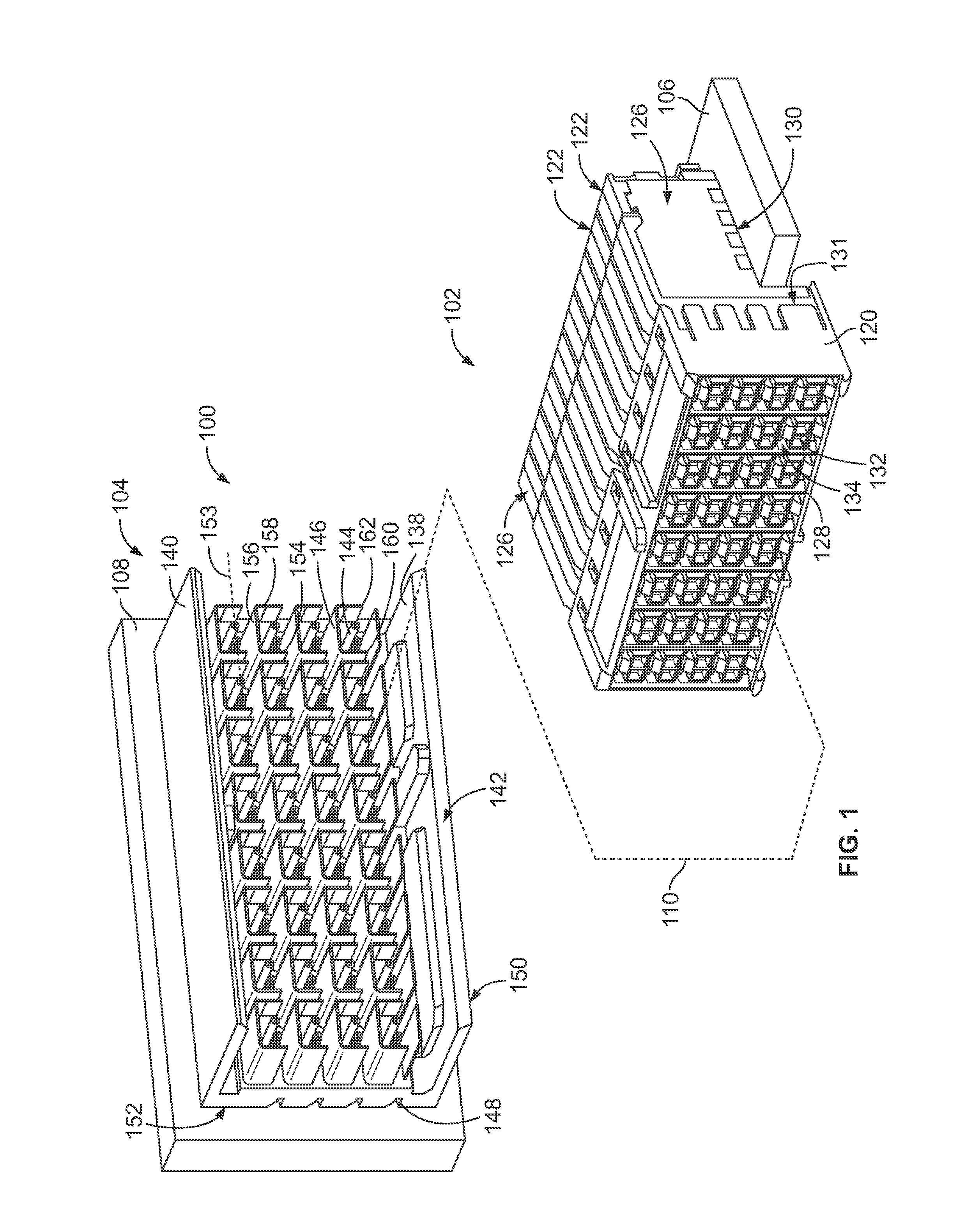
[0016]FIG. 1 is a perspective view of an exemplary embodiment of an electrical connector system 100 illustrating a receptacle assembly 102 and a header assembly 104 that may be directly mated together. The receptacle assembly 102 and / or the header assembly 104 may be referred to hereinafter individually as a “connector assembly” or collectively as “connector assemblies”. The receptacle and header assemblies 102, 104 are each electrically connected to respective circuit boards 106, 108. The receptacle and header assemblies 102, 104 are utilized to electrically connect the circuit boards 106, 108 to one another at a separable mating interface. In an exemplary embodiment, the circuit boards 106, 108 are oriented perpendicular to one another when the receptacle and header assemblies 102, 104 are mated. Alternative orientations of the circuit boards 106, 108 are possible in alternative embodiments.

[0017]A mating axis 110 extends through the receptacle and header assemblies 102, 104. The ...


PUM


Abstract

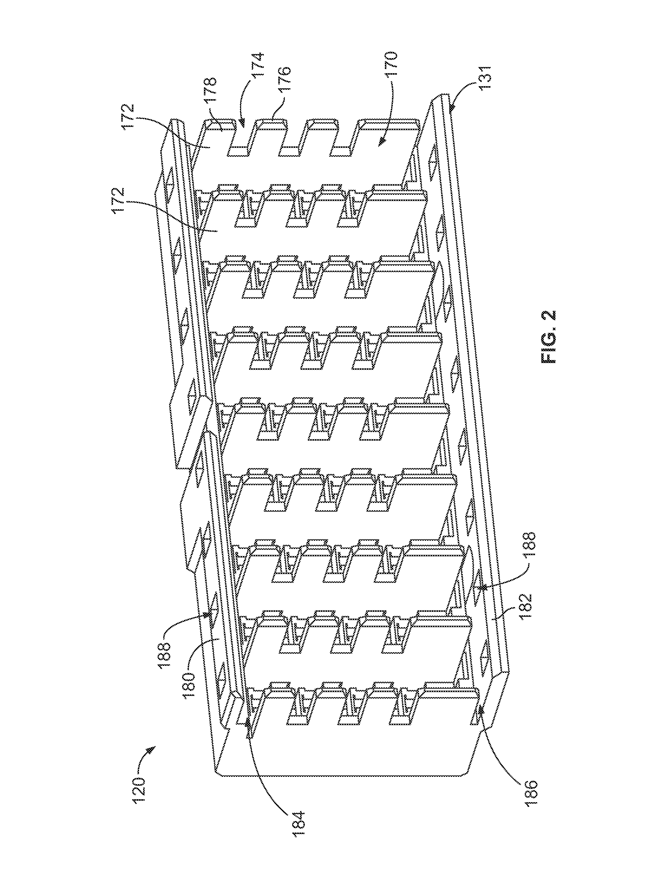
A receptacle assembly includes a front housing having a mating end and a loading end. The front housing has pockets at the loading end separated by separating walls having slots therethrough open at rears thereof. The front housing receives contact modules in corresponding pockets each having a holder holding a plurality of contacts between first and second side walls. The holders have embossments extending from the first side walls proximate to the fronts of the holders. The embossments are loaded into corresponding slots through the rears of the separating walls to control positions of the contact modules with respect to the front housing.

Description

BACKGROUND OF THE INVENTION[0001]The subject matter herein relates generally to a connector assembly having contact modules.[0002]Some electrical systems utilize electrical connectors to interconnect two circuit boards, such as a motherboard and daughtercard. Signal loss and / or signal degradation is a problem in known electrical systems. For example, cross talk results from an electromagnetic coupling of the fields surrounding an active conductor or differential pair of conductors and an adjacent conductor or differential pair of conductors. The strength of the coupling generally depends on the separation between the conductors, thus, cross talk may be significant when the electrical connectors are placed in close proximity to each other. Moreover, as speed and performance demands increase, known electrical connectors are proving to be insufficient. Additionally, there is a desire to increase the density of electrical connectors to increase throughput of the electrical system, witho...

Claims


Application Information

Patent Timeline
IPC IPC(8): H01R13/648
CPCH01R12/724H01R13/514H01R13/6471H01R13/6586
Inventor WHITEMAN, JR., ROBERT NEILDAVIS, WAYNE SAMUEL
Owner TYCO ELECTRONICS LOGISTICS AG (CH)
Learn More