Biomass dryer/burner system

a biomass dryer and burner technology, applied in the field of air treatment, can solve the problems of insufficient cost savings in environmental benefits for project owners, inefficient pollution control equipment to control emissions from biomass combustion, and inconvenient design of combustion units, etc., and achieve the effect of moistening emissions

Active Publication Date: 2013-07-02
VALENTE PETER
View PDF11 Cites 2 Cited by
  • Summary
  • Abstract
  • Description
  • Claims
  • Application Information

AI Technical Summary

Problems solved by technology

However, these conversions have typically been made without adequate research, and problems associated with the conversion process have resulted in the project owner not fully realizing the cost savings in environmental benefits that are anticipated to result from the conversion.
The major problems encountered include the ability to source “dry wood” as a biomass fuel supply, inappropriately designed combustion units, and inefficient pollution control equipment to control emissions from biomass combustion.
Wood removed under this program is chipped and used in biomass burners without adequate seasoning to allow the wood to dry out.
Burning of green wood results in a significantly reduced energy of the biomass burner which in turn results in fouling of the combustion unit from creosote buildup and increased atmosphere pollution associated with the burning of biomass.
Previously known bag systems are not capable of cleaning moist air, or an air / water mixture.
Bag systems are only capable of filtering emissions from a biomass dryer / burner system emitting dry air emissions.
While the conversion from fossil fuels to biomass often results in cost savings and environmental benefits, the environmental benefits are not realized unless the emissions from the biomass burner are neutralized to government air emission standards.

Method used


Image

  • Biomass dryer/burner system
  • Biomass dryer/burner system
  • Biomass dryer/burner system

Examples


Embodiment Construction

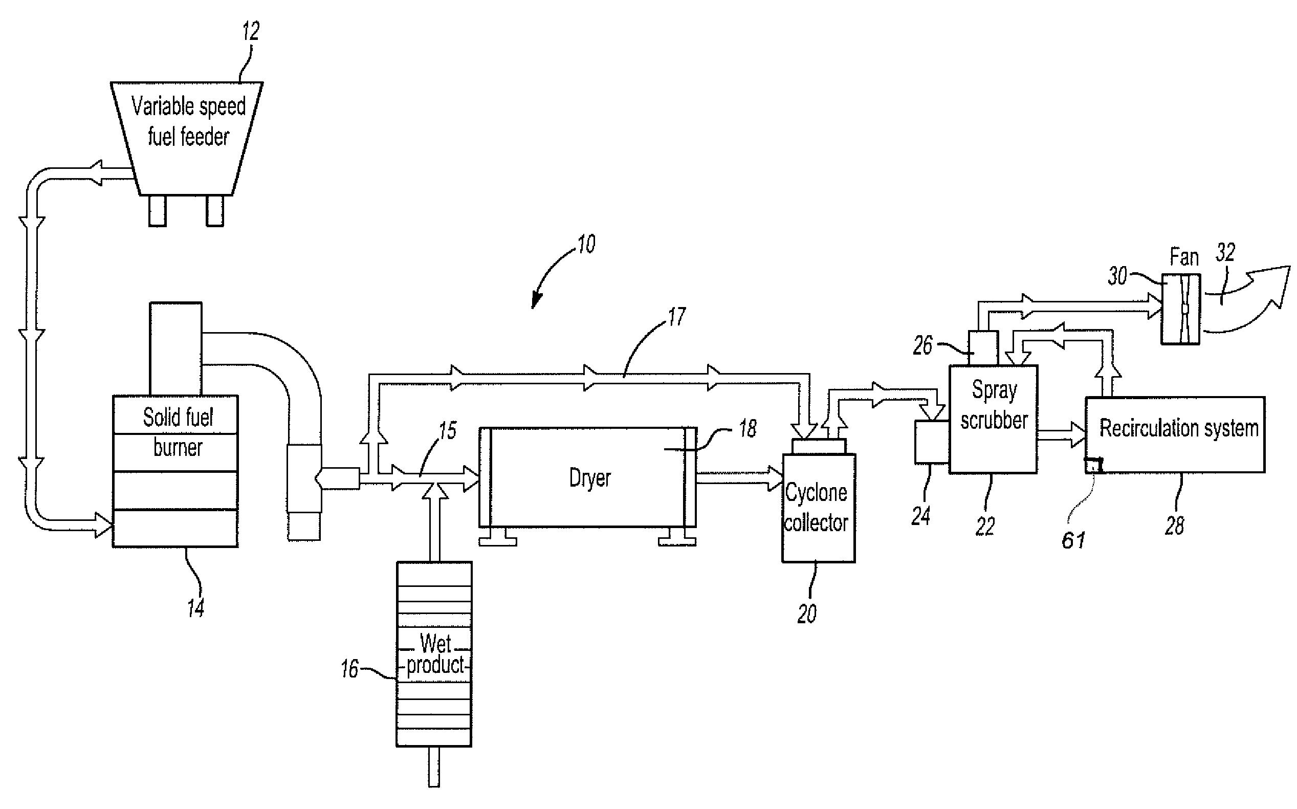
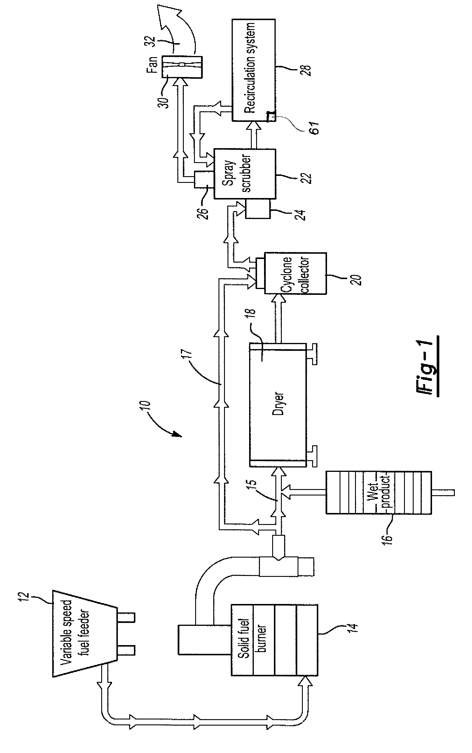
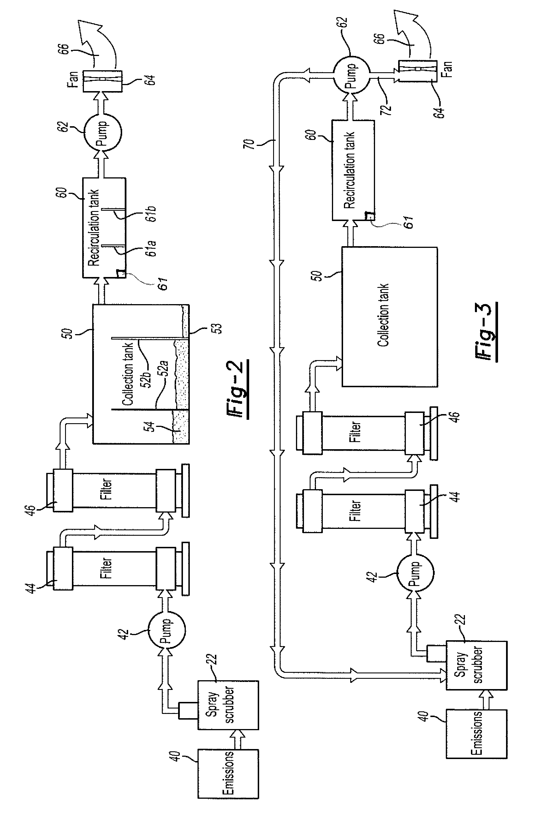
[0015]The present invention provides a biomass dryer / burner system which efficiently and effectively dries or burns biomass and subsequently cleans the emissions produced during burning or drying by means of an attached air cleaning apparatus. Emissions produced from the burning or drying process, in turn, heat water used to generate steam, the steam in turn generates electricity. Emissions are carefully scrubbed to eliminate particulate matter and other contaminants before exhausting the air / water mixture to the atmosphere.

[0016]The biomass dryer / burner system includes a variable speed fuel burner 12 and a solid fuel burner 14. The burner 14 is a 10 mmBTU per hour cyclonic biomass burner designed to burn construction and demolition waste. The burner 14 is of a wood fired burner type which has a high capacity and produces a temperature of 595°. Biomass material is introduced into one end of the rotary drum on the biomass burner 14. The drum has a diameter of approximately 7 feet and...


PUM

PropertyMeasurementUnit
lengthaaaaaaaaaa
lengthaaaaaaaaaa
velocityaaaaaaaaaa

Abstract

The present invention provides a biomass dryer / burner having an air cleaning apparatus adapted to accept emissions from the biomass dryer / burner and to convert said emissions to clean air to meet government emission standards. The biomass dryer / burner unit includes a dryer adapted to dry biomass, such as demolition waste or cut trees. The biomass dryer / burner unit optionally including a burner adapted to burn biomass. The biomass dryer / burner further producing emissions requiring cleaning before exhausting to the atmosphere. The air cleaning apparatus including a spray scrubber fluidly connected to the biomass dryer / burner adapted to moisten emissions, a recirculation tank in fluid communication with a collection tank, and the recirculation tank further having a sensor adapted to measure contaminant levels contained within the recirculation air filtration system. The sensor contained within the recirculation tank measures levels of carbon monoxide. If the air contained within the recirculation air filtration system measures above a predetermined contaminant level, then the air contained within the recirculation air filtration system is directed back into the spray scrubber. If the air contained within the recirculation air filtration system is below a predetermined level, then the air is exhausted into the atmosphere.

Description

CROSS-REFERENCE TO RELATED APPLICATIONS[0001]This application claims priority of U.S. Provisional Patent Application Ser. No. 61 / 151,229 filed Feb. 10, 2009, which is incorporated herein by reference.FIELD OF THE INVENTION[0002]The present invention relates to air treatment. In particular this invention relates to the treatment of emissions from a biomass dryer / burner system.BACKGROUND OF THE INVENTION[0003]The burning of biomass in the form of construction and demolition wood residue and wood generated from logging and pest control activities has been a substantial increase over the past several years. As the cost of fossil fuels (e.g. fuel oil, bunker oil, and natural gas) has increased, many large-scale users of these fossil fuels have looked to biomass as an alternative to provide a cost-effective fuel to supply their energy needs.[0004]Large scale commercial greenhouses in particular have been on the forefront of the conversion to biomass fuel as a replacement for natural gas a...

Claims


Application Information

Patent Timeline
Patent Type & Authority Patents(United States)
IPC IPC(8): B01D53/14
CPCB01D53/14B01D53/78F26B25/005B01D53/77B01D2257/502F26B2200/02
Inventor VALENTE, PETER
Owner VALENTE PETER
Why Eureka
Try Eureka