
System and method for automatically aligning a telescope without requiring user intervention

a technology of automatic alignment and telescope, applied in the direction of instruments, optical elements, angle measurement, etc., can solve the problems of telescopes that cannot be automatically aligned, telescopes that cannot introduce additional complexity and cost, and apparatus that cannot be accurately positioned

Active Publication Date: 2013-07-02
CELESTRON ACQUISITION
View PDF63 Cites 4 Cited by
  • Summary
  • Abstract
  • Description
  • Claims
  • Application Information

AI Technical Summary

Benefits of technology

The present invention provides a system and method for automatically aligning a telescope without requiring knowledge of local time or geographic location. This means that the system can work even when bright stars are not visible. The technique avoids the need for additional equipment such as GPS systems and digital compasses, and does not require user intervention. The iterative optimization process of the invention eliminates the need for GPS, avoids the need for manual input, and does not require information about the local horizon coordinate system. Overall, the invention improves the efficiency, ease of use, and cost-effectiveness of telescope alignment.

Problems solved by technology

Accordingly, in general, accurate GoTo pointing operations cannot take place until the telescope has been properly aligned.
The requirement for independent bright reference stars can increase the time to achieve an alignment, and can cause the apparatus to fail to align in situations where it is not possible to detect a sufficient number of bright reference stars.
However, these telescopes can introduce additional complexity and cost, as the final product must include such components as the GPS, digital compass, accelerometer, and image capture devices.
Finally, at least some telescopes of this type use star brightness in their determination of the alignment reference position, which introduce similar limitations to those discussed above in connection with McWilliams.
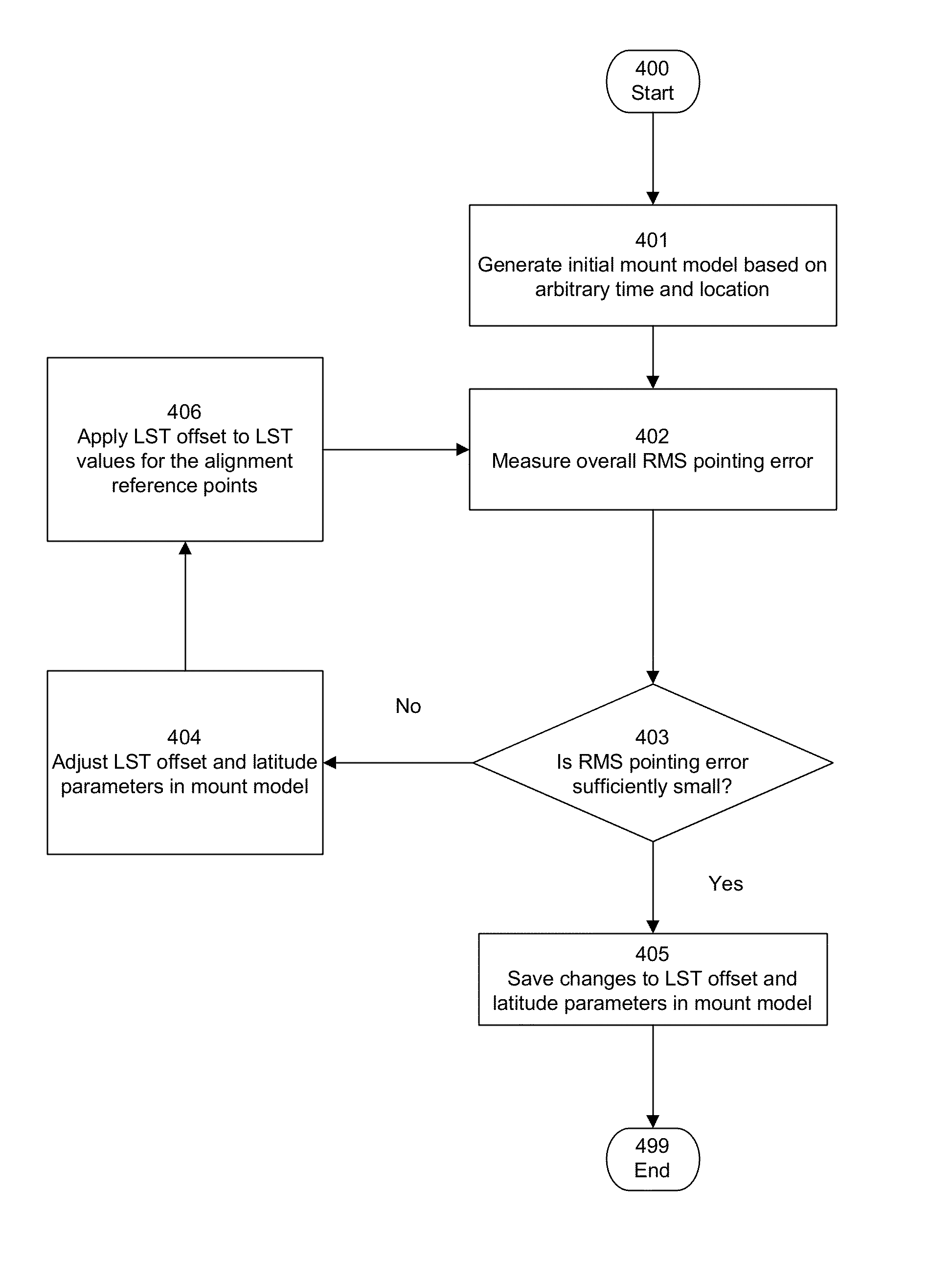
Because the actual time and location are not used, it is expected that there will be a measurable error in the pointing model due to the LST offset (difference between actual LST and LST derived from the initial arbitrary time and location) and the latitude error (difference between actual latitude and initial arbitrary latitude).

Method used


Image

  • System and method for automatically aligning a telescope without requiring user intervention
  • System and method for automatically aligning a telescope without requiring user intervention
  • System and method for automatically aligning a telescope without requiring user intervention

Examples


Embodiment Construction

[0030]For purposes of the description provided herein, all references to “time” can be considered to refer to both “date and time”, where appropriate.

System Architecture

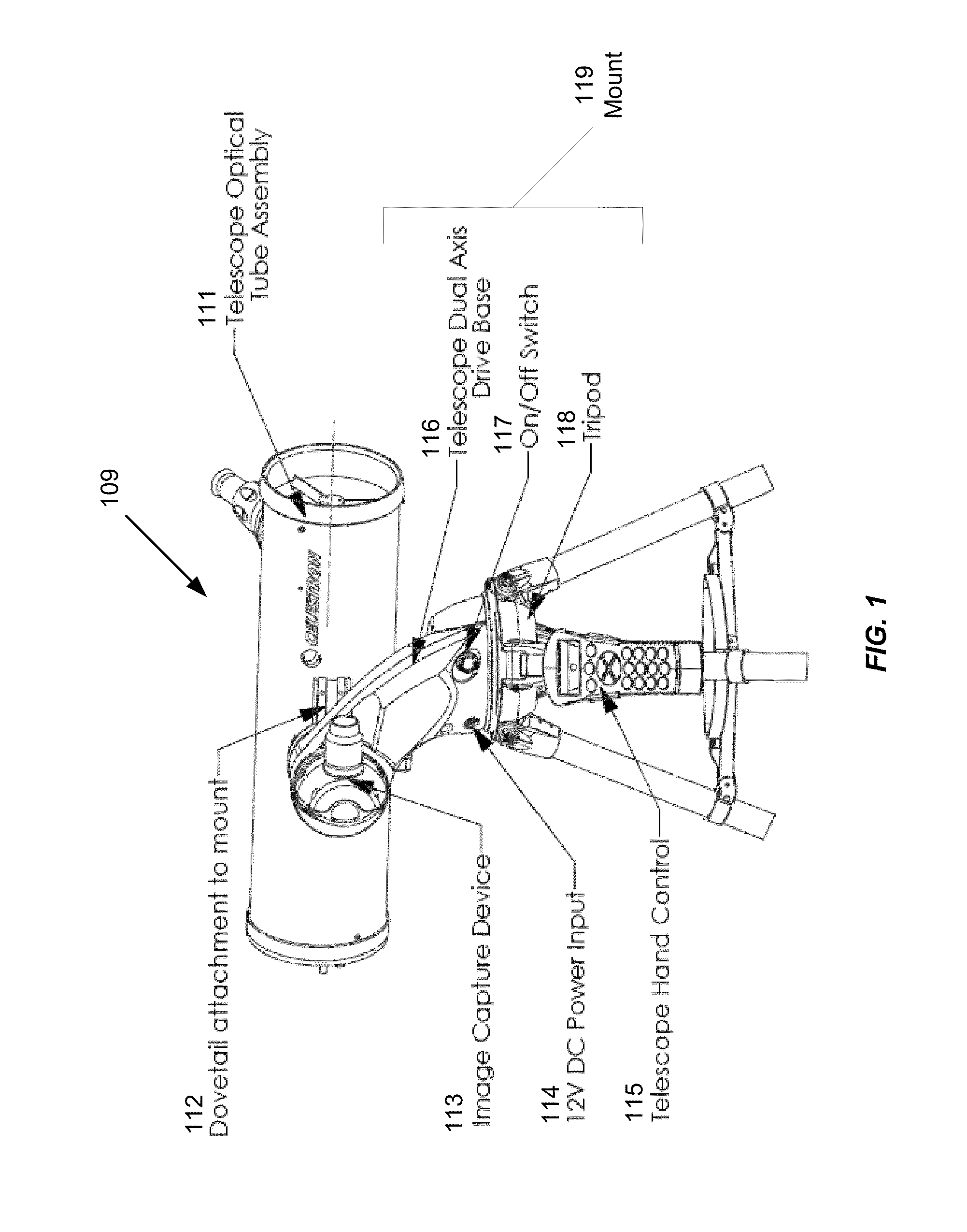
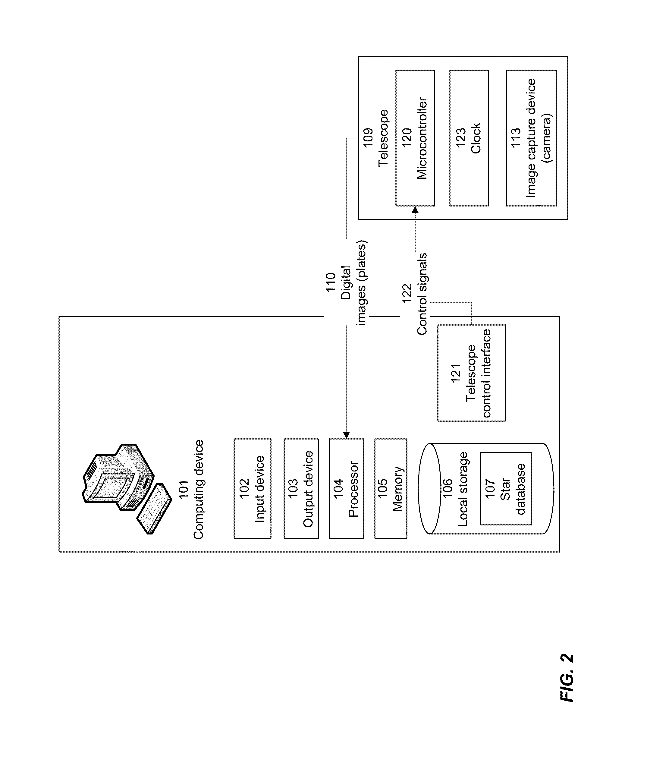
[0031]According to various embodiments, the present invention can be implemented within a telescope or other device for generating or capturing celestial images, and / or within a mount or other apparatus for controlling and adjusting the positioning of such a telescope. According to other embodiments, the present invention can be implemented within a computing device or other electronic device that can be communicatively coupled with a telescope or other imaging device, for example to send signals to a microcontroller for controlling and adjusting the positioning of the telescope.

[0032]According to other embodiments, the present invention can be implemented in a device that is mechanically coupled to a telescope and which adjusts the position of the telescope, for example by mechanical coupling with the telescope moun...


PUM


Abstract

According to various embodiments, a telescope is automatically aligned without requiring user intervention and without requiring knowledge of actual local time or location. A mount model specifying a relationship between a telescope's internal coordinate system and a celestial coordinate system is generated using an arbitrary time, arbitrary telescope location, and a number of alignment reference points. A pointing error for the initial mount model is determined, for example using a plate solving technique to translate between plate coordinates and celestial coordinates for the alignment reference points. Time and location values are iteratively adjusted to reduce the pointing error until it is acceptably low. In one embodiment, adjustments are made by reference to a local sidereal time (LST) offset and / or a latitude value. In one embodiment, the iterative adjustment is performed using a two-phase methodology, including a coarse adjustment followed by a fine adjustment.

Description

CROSS-REFERENCE TO RELATED APPLICATION[0001]This invention is related to U.S. patent application Ser. No. 12 / 983,065 for “Determining Celestial Coordinates for an Image”, filed on the same date as the present application. The related application is incorporated herein by reference.FIELD OF THE INVENTION[0002]The present invention relates to methods and systems for automatically aligning a telescope to point to a desired celestial location.DESCRIPTION OF THE RELATED ART[0003]Many telescopes are capable of automatically pointing to particular coordinates given in terms of right ascension and declination, and / or to specified celestial objects by looking up the celestial coordinate locations of such objects in a database. Such operations are usually enabled by the use of a specialized motor-driven mount and associated software for controlling the positioning of the mount via a microprocessor or other control device. Such an apparatus is generally referred to as a “GoTo” mount.[0004]In g...

Claims


Application Information

Patent Timeline
Patent Type & Authority Patents(United States)
IPC IPC(8): G02B23/00
CPCG01S3/7867G02B23/16
Inventor MEDLEY, DANYAL
Owner CELESTRON ACQUISITION
Learn More