Storage system and control method
a storage system and control method technology, applied in the field of storage systems, can solve the problems of not being able to allocate a real storage area from the first pool, affecting the logical volume, and not being able to write data into the other logical devices of the server computer, so as to achieve the effect of improving the functionality of the computer system, and facilitating and promptly
- Summary
- Abstract
- Description
- Claims
- Application Information
AI Technical Summary
Benefits of technology
Problems solved by technology
Method used
Image
Examples
first embodiment
(1) First Embodiment
(1-1) Configuration of Computer System in Present Embodiment
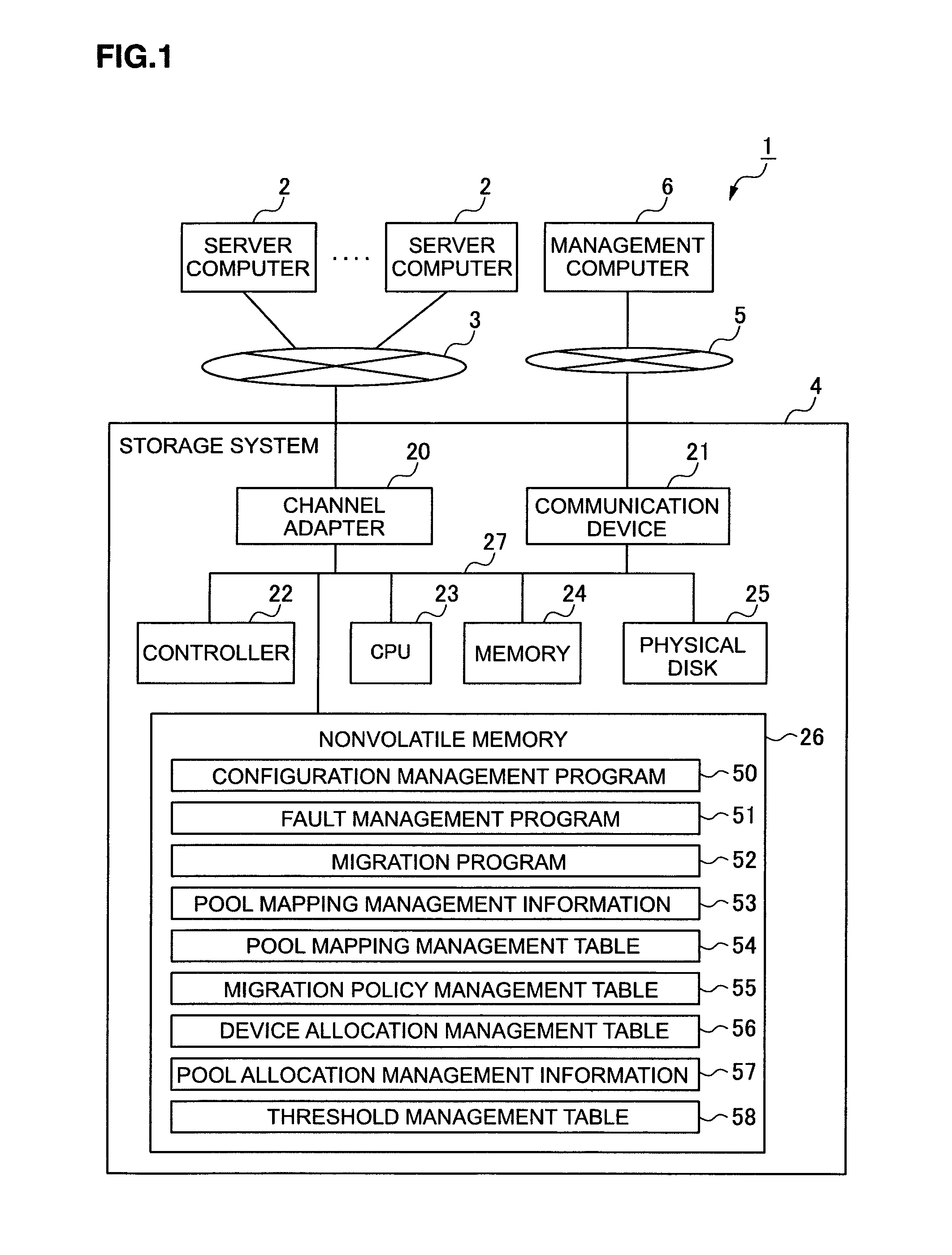
[0039]FIG. 1 shows the overall computer system 1 according to this embodiment. The computer system 1 is configured by one or more server computers 2 being connected to a storage system 4 via a first speed network 3, and a management computer 6 being connected to the storage system 4 via a second speed network 5.
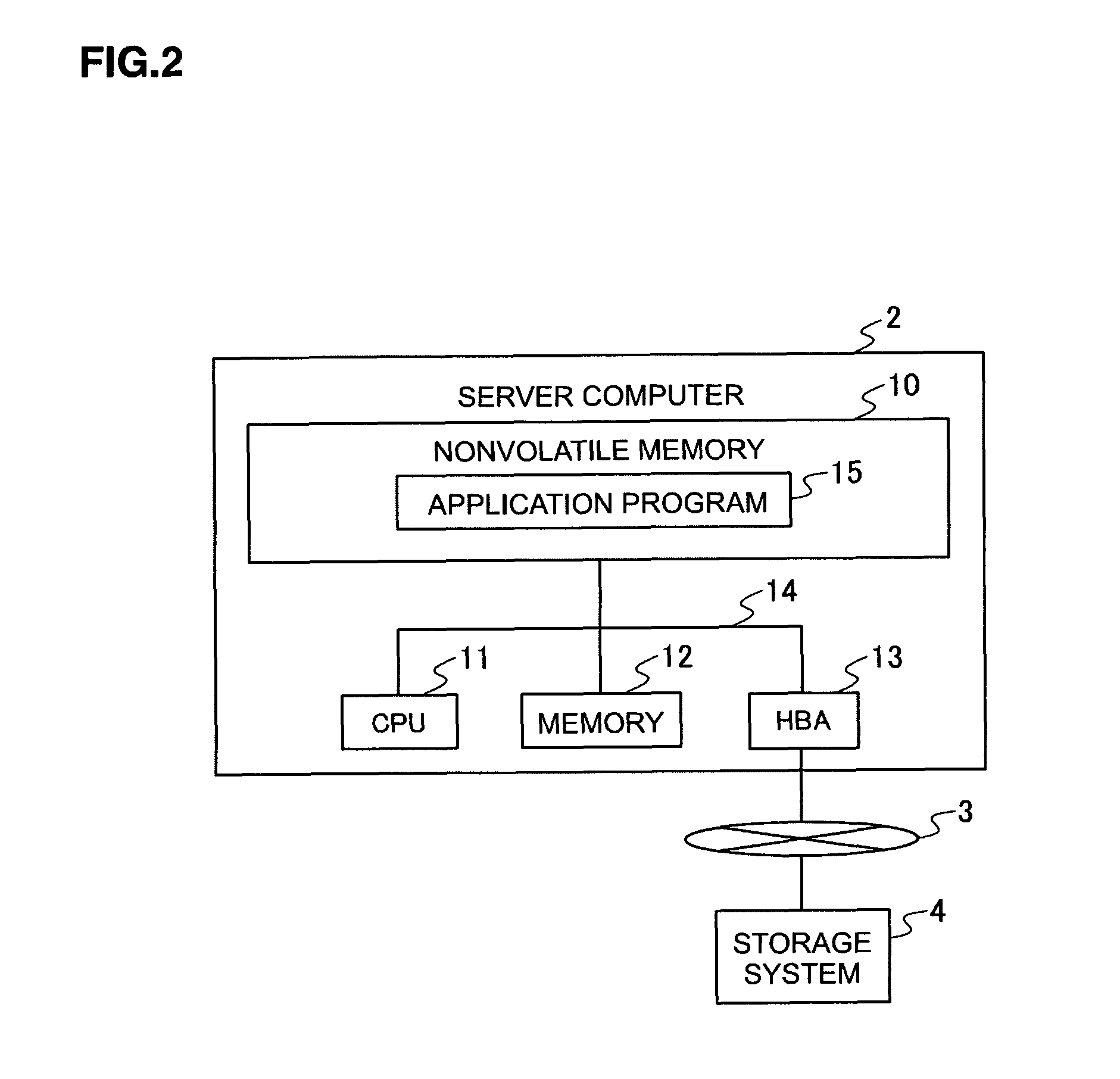
[0040]The server computer 2 comprises, as shown in FIG. 2, a nonvolatile memory 10, a CPU (Central Processing Unit) 11, a memory 12 and a host bus adapter (HBA) 13, and is configured by these components being mutually connected via a system bus 14.
[0041]The nonvolatile memory 10 stores an application program 15 in addition to the various types of programs including an OS (Operating System) required for operating the server computer 2, as well as various types of data. When the application program 15 is executed, the server computer 2 read and writes data from and into the storage system 4. Inciden...
second embodiment
(2) Second Embodiment
[0152]FIG. 16, in which the components corresponding to those of FIG. 1 are respectively given the same reference numerals, shows a computer system 80 according to the second embodiment. The computer system 80 is configured the same as the computer system 1 (FIG. 1) according to the first embodiment excluding the point that a plurality of reserved physical disks 82 are provided to the storage system 81, and the point that a pool expansion program 83 and a pool expansion management table 84 are additionally stored in the nonvolatile memory 26 of the storage system 81.
[0153]The reserved physical disk82 is configured, as with the physical disk 25, from an expensive disk such as a SCSI disk or an inexpensive disk such as a SATA (Serial AT Attachment) disk or an optical disk. These reserved physical disks 82 are associated with any one of the pools 41 in advance, and are used to expand the associated pool 41.
[0154]The pool expansion program 83 is a program for tempor...
third embodiment
(3) Third Embodiment
[0171]FIG. 19, in which the components corresponding to those of FIG. 16 are respectively given the same reference numerals, shows a computer system 90 according to the third embodiment. The computer system 90 is configured the same as the computer system 80 according to the second embodiment excluding the point that a pool reconstruction program 92 is stored in the nonvolatile memory 26 of the storage system 91.
[0172]The pool reconstruction program 92 is a program for returning data stored in another pool 41 (pool 41 which should have moved data to the pool 41 subject to a failure in the second embodiment) during the occurrence of a fault of that pool 41 after the fault recovery thereof to the primary pool (pool subject to a fault) 41, and returning the status of the other pool 41 to a normal state.
[0173]FIG. 20 shows the processing routine of the pool reconstruction processing to be executed by the CPU 23 of the storage system 91 based on the pool reconstructio...
PUM
 Abstract
Description
Claims
Application Information
 - R&D
- Intellectual Property
- Life Sciences
- Materials
- Tech Scout
- Unparalleled Data Quality
- Higher Quality Content
- 60% Fewer Hallucinations
Browse by: Latest US Patents, China's latest patents, Technical Efficacy Thesaurus, Application Domain, Technology Topic, Popular Technical Reports.
© 2025 PatSnap. All rights reserved.Legal|Privacy policy|Modern Slavery Act Transparency Statement|Sitemap|About US| Contact US: help@patsnap.com


