Blowing-mode door for vehicle air-conditioning apparatus and vehicle air-conditioning apparatus using the same

a technology of vehicle air conditioner and blower, which is applied in the direction of vehicle components, vehicle heating/cooling devices, air-flow control members, etc., can solve the problems of reducing the independent temperature-adjusting performance, affecting the temperature-adjustment performance, and affecting the ability to increase the thickness of only the rotating shaft, so as to reduce the leakage of temperature-adjusted air, improve the torsional rigidity of the portion, and reduce the strength of the door

Active Publication Date: 2013-07-09
MITSUBISHI HEAVY IND LTD
View PDF20 Cites 3 Cited by
  • Summary
  • Abstract
  • Description
  • Claims
  • Application Information

AI Technical Summary

Benefits of technology

[0009]To ensure the independent temperature-adjusting performance in the vehicle air-conditioning apparatus of the system involving adjusting the temperatures of the individual air channels, it is important to reduce leakage (circulation) of temperature-adjusted air between the plurality of air channels as much as possible. If a large amount of temperature-adjusted air leaks, when the temperature in one air channel is adjusted, the temperature in the other air channel is changed along therewith, so that the independent temperature-adjusting performance is impaired. With the structure in which a large communication hole for inserting the mode door is provided between the partition plate and the air-conditioner case, as in the above-described Patent Document 1, leakage of temperature-adjusted air through the communication hole cannot be prevented, posing the problem of degrading the independent temperature-adjusting performance. The structures shown in Patent Documents 2 and 3 improve the independent temperature-adjusting performance by eliminating such a communication hole.
[0010]Meanwhile, for the blowing-mode doors, a resin door in which the rotating shaft and the pair of left and right plate-like doors are molded in one piece is used. These mode doors are generally manufactured by injection molding. However, if there is an extreme difference in the wall thickness of the molded portion, deformation due to shrinkage tends to occur, causing a gap when the air outlets are opened and closed. Therefore, it is difficult to increase the thickness of only the rotating shaft to thereby improve the rigidity of the doors because of molding restrictions. The mode doors are provided with elastic sealing members, and when the air outlets are opened and closed, a rotational torque is applied to one end of the rotating shaft(s) by an actuator to press the elastic sealing members against the case and sealing surfaces of the partition plate. Therefore, if the rigidity of the rotating shaft is low, the rotating shaft is twisted due to the reaction force of the elastic sealing member, generating gaps at the sealing portions. In particular, the above-described mode doors tend to decrease in torsional rigidity at the center of the rotating shafts because a gap is formed between the left and right plate-like doors, so that the sealing performance at the plate-like door provided at the other end of the rotating shaft tends to be decreased. These gaps also cause leakage of temperature-adjusted air, reducing the independent temperature-adjusting performance.

Problems solved by technology

If a large amount of temperature-adjusted air leaks, when the temperature in one air channel is adjusted, the temperature in the other air channel is changed along therewith, so that the independent temperature-adjusting performance is impaired.
With the structure in which a large communication hole for inserting the mode door is provided between the partition plate and the air-conditioner case, as in the above-described Patent Document 1, leakage of temperature-adjusted air through the communication hole cannot be prevented, posing the problem of degrading the independent temperature-adjusting performance.
However, if there is an extreme difference in the wall thickness of the molded portion, deformation due to shrinkage tends to occur, causing a gap when the air outlets are opened and closed.
Therefore, it is difficult to increase the thickness of only the rotating shaft to thereby improve the rigidity of the doors because of molding restrictions.
Therefore, if the rigidity of the rotating shaft is low, the rotating shaft is twisted due to the reaction force of the elastic sealing member, generating gaps at the sealing portions.
In particular, the above-described mode doors tend to decrease in torsional rigidity at the center of the rotating shafts because a gap is formed between the left and right plate-like doors, so that the sealing performance at the plate-like door provided at the other end of the rotating shaft tends to be decreased.
These gaps also cause leakage of temperature-adjusted air, reducing the independent temperature-adjusting performance.
However, this structure cannot ensure sufficient torsional strength because the thickness of the rotating shaft cannot be increased, so that there is the possibility that the rotating shaft is twisted due to the reaction force of the elastic sealing member because of the insufficient rigidity of the rotating shaft, thus generating gaps on the sealing surfaces.
Accordingly, there still remains a problem in bypassing temperature-adjusted air due to the insufficient strength of the mode doors.
Therefore, this arc-shaped notch serves as a leakage gap for the temperature-adjusted air, which inevitably degrades the independent temperature-adjusting performance.

Method used


Image

  • Blowing-mode door for vehicle air-conditioning apparatus and vehicle air-conditioning apparatus using the same
  • Blowing-mode door for vehicle air-conditioning apparatus and vehicle air-conditioning apparatus using the same
  • Blowing-mode door for vehicle air-conditioning apparatus and vehicle air-conditioning apparatus using the same

Examples


first embodiment

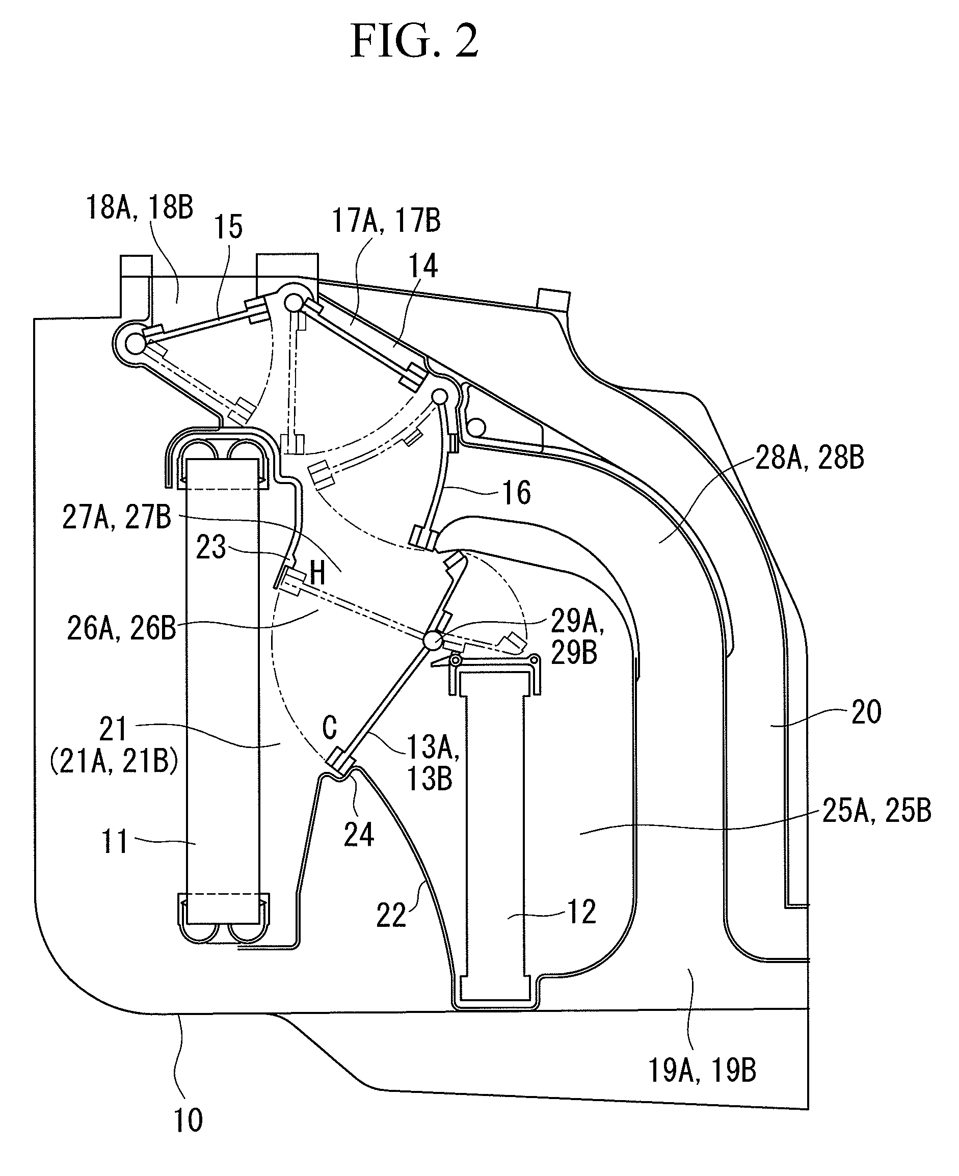
[0069]A first embodiment of the present invention will be described hereinbelow with reference to FIGS. 1 to 7D.

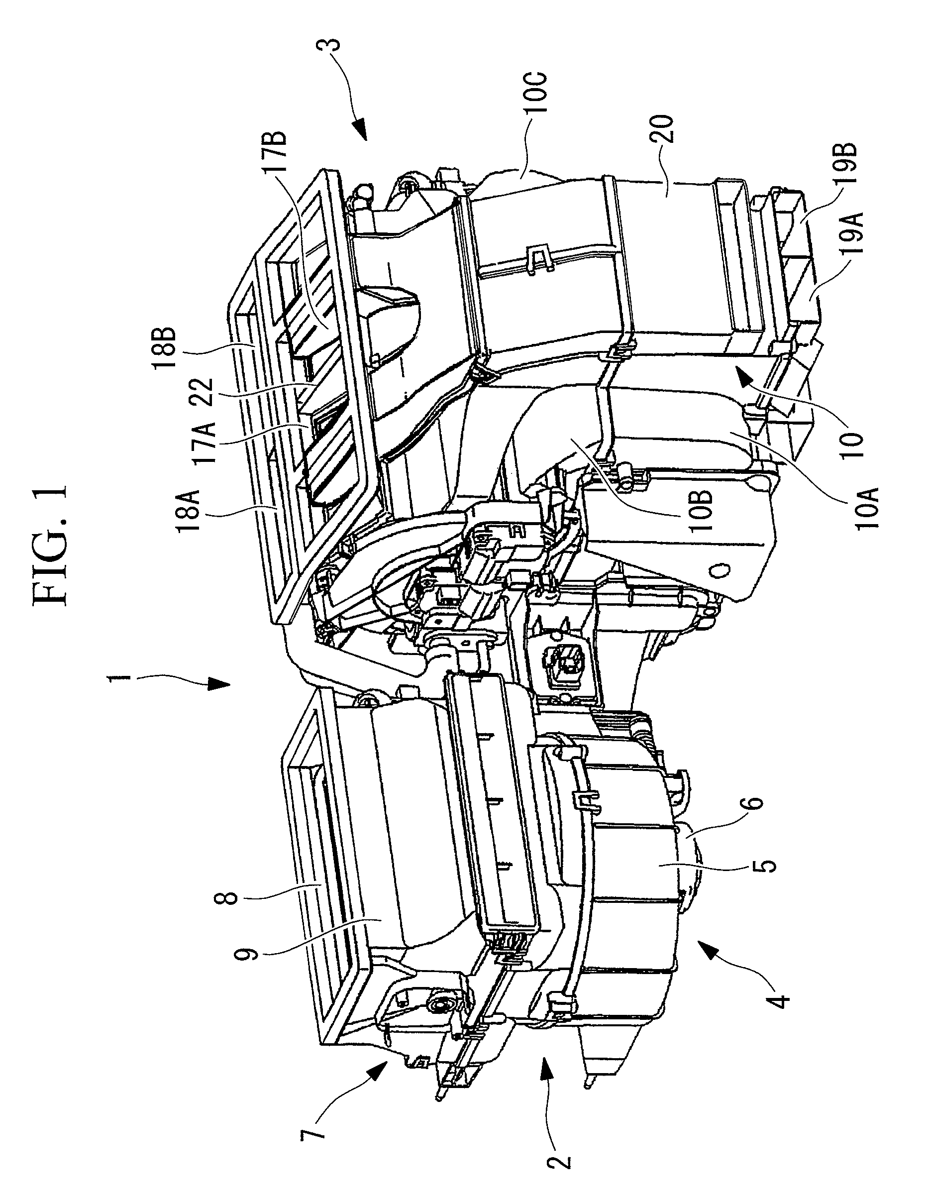
[0070]FIG. 1 shows an external perspective view of a vehicle air-conditioning apparatus 1 according to the first embodiment of the present invention. The vehicle air-conditioning apparatus 1 is constituted of an air-blowing unit 2 that intakes external air from the exterior of the vehicle or internal air from the interior of the vehicle cabin and sends the air to the downstream side and an air-conditioning unit (HVAC unit) 3 connected to the downstream side of the air-blowing unit 2 and adjusts the temperature of the air sent from the air-blowing unit 2 to a set temperature and blows it into the vehicle cabin.

[0071]The air-blowing unit 2 is constituted of a centrifugal air blower 4 provided with an impeller (not shown) driven by a motor 6 in a casing 5 and an internal / external-air switching unit 7 connected to an air inlet of the casing 5. The internal / external-air switchi...

second embodiment

[0099]Next, a second embodiment of the present invention will be described with reference to FIGS. 7C and 7D.

[0100]This embodiment differs from the above-described first embodiment in the structure of rotating shafts 50 of the blowing-mode doors 14 to 16. Since the other features are the same as those of the first embodiment, descriptions thereof will be omitted.

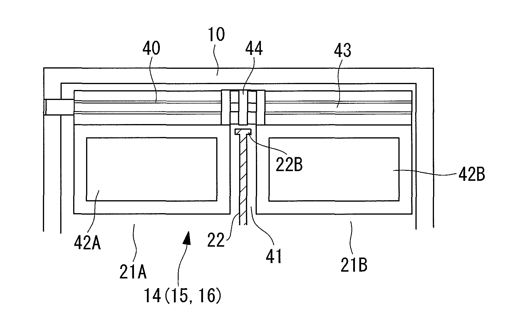
[0101]The rotating shaft 50 of this embodiment is configured such that ribs 53 provided around the shaft are provided only in the direction parallel to the plate-like doors 42A and 42B (see FIG. 7C) or only in the direction perpendicular to the plate-like doors 42A and 42B (see FIG. 7D). Circular ribs 54 that connect the ribs 53 together are provided with a predetermined pitch at three locations corresponding to the gap 41 in the center of the rotating shaft 50, as in the first embodiment.

[0102]The structure in which the rotating shaft 50 is provided with the ribs 53 and the circular ribs 54 as in the above can also provide ...


PUM


Abstract

There are provided a blowing-mode door for a vehicle air-conditioning apparatus in which leakage of temperature-adjusted air can be prevented to improve independent temperature-adjusting performance by minimizing the gap between the mode door and a partition plate and increasing the rigidity of the mode door, as well as a vehicle air-conditioning apparatus using the same. A blowing-mode door applied to a vehicle air-conditioning apparatus with an independent temperature-adjusting system is provided in which the blowing-mode door includes a rotating shaft having a predetermined length and a pair of left and right plate-like doors that are molded integrally with the rotating shaft, with a gap for preventing interference with a partition plate therebetween.

Description

TECHNICAL FIELD[0001]The present invention relates to a blowing-mode door applied to a vehicle air-conditioning apparatus in which an air channel formed in a case is partitioned into a plurality of channels by a partition plate so that the temperature of the air channels can be adjusted independently, as well as to an independent-temperature-adjusting vehicle air-conditioning apparatus using the same.BACKGROUND ART[0002]A known vehicle air-conditioning apparatus is provided with a partition plate in an air-conditioner case to partition the air channel into a plurality of channels so that the temperature of the air channels can be adjusted independently. This vehicle air-conditioning apparatus is configured to blow temperature-adjusted air independently, for example, to the driver seat and the passenger seat of the vehicle. This is generally configured such that an air channel downstream of an evaporator disposed in the air-conditioner case is partitioned into two left and right chan...

Claims


Application Information

Patent Timeline
Patent Type & Authority Patents(United States)
IPC IPC(8): B60H1/00
CPCB60H1/00678B60H2001/00135B60H2001/00714F24F13/14B60H2001/00707
Inventor TANAKA, YASUNARISIBATA, TOMOHIKO
Owner MITSUBISHI HEAVY IND LTD
Why Eureka
Try Eureka