Divided wall columns for smaller sized plants

a technology for divided wall columns and plants, applied in vacuum distillation separation, separation processes, lighting and heating apparatus, etc., can solve problems such as troublesome operation, upset conditions, and difficult to meet the requirements of small-scale production and design, and achieve the effect of facilitating the use of divided wall technology and small column diameter

Active Publication Date: 2013-07-09
AIR PROD & CHEM INC
View PDF20 Cites 43 Cited by
  • Summary
  • Abstract
  • Description
  • Claims
  • Application Information

AI Technical Summary

Benefits of technology

[0010]Embodiments of the present invention satisfy a need in the art by providing an apparatus and method for facilitating the use of divided wall technology with the specific advantage of providing for the production of smaller column diameters than are currently manufactured or used.

Problems solved by technology

The previous methods of manufacture and designs of divided wall columns for smaller sized applications, however, are problematic for several reasons.
First, use of a divided wall column incorporating a traditional dividing wall subjects the dividing wall to both pressure and temperature differences on both sides of the divided wall column.
The pressure and temperature differences especially are significant during operating upsets, for example, during the startup or shut down of the facility.
These upset conditions can be especially problematic when the operating temperatures of the column system deviate substantially from ambient conditions.
Use of these support or stiffening members, however, may increase the cost and have a detrimental effect on the efficiency of the distillation process.
Increasing the thickness of the dividing wall to compensate for the mechanical stresses has also been attempted, however, the increase in strength realized is minimal, especially in columns having large diameters.
Further, increasing the diameter of the dividing wall also leads to complications associated with the welding of the dividing wall to the column wall.
Increasing the thickness of the dividing wall also causes occupation of a greater portion of the column area leading to less efficient use of the available area.
Use of double (laminated) or honeycombed walls, strengthening ribs, or using distillation trays as stiffeners to strengthen the dividing wall all suffer from the same drawbacks described above.
Second, with the increased demand for divided wall columns to be smaller, the space available for a welder to enter the pressure shell column and weld the dividing wall to the pressure shell column or the half-cylindrical shell to the dividing wall itself is problematic.
In addition, welding shims, support members and / or stiffening members inside these small traditional divided wall columns is increasingly difficult.

Method used


Image

  • Divided wall columns for smaller sized plants
  • Divided wall columns for smaller sized plants
  • Divided wall columns for smaller sized plants

Examples


Embodiment Construction

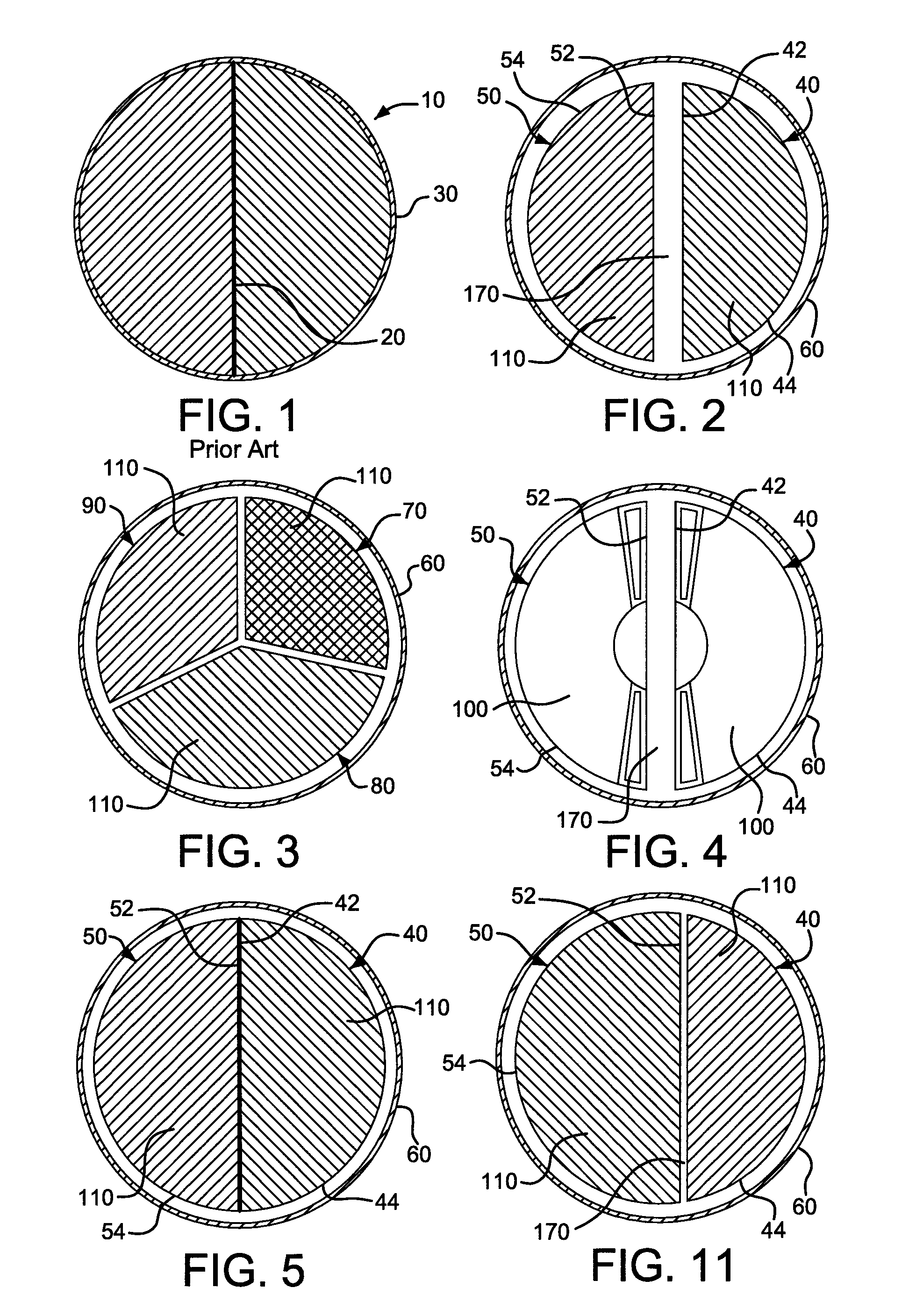
[0035]FIG. 1 illustrates a known traditional divided wall column 10 where a dividing wall 20 is welded to column 30.

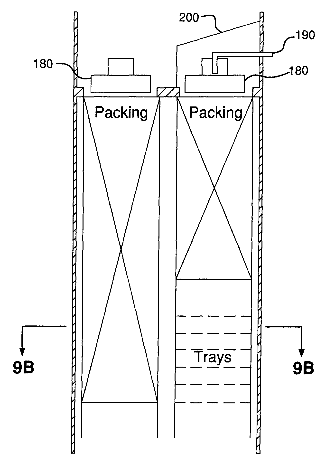
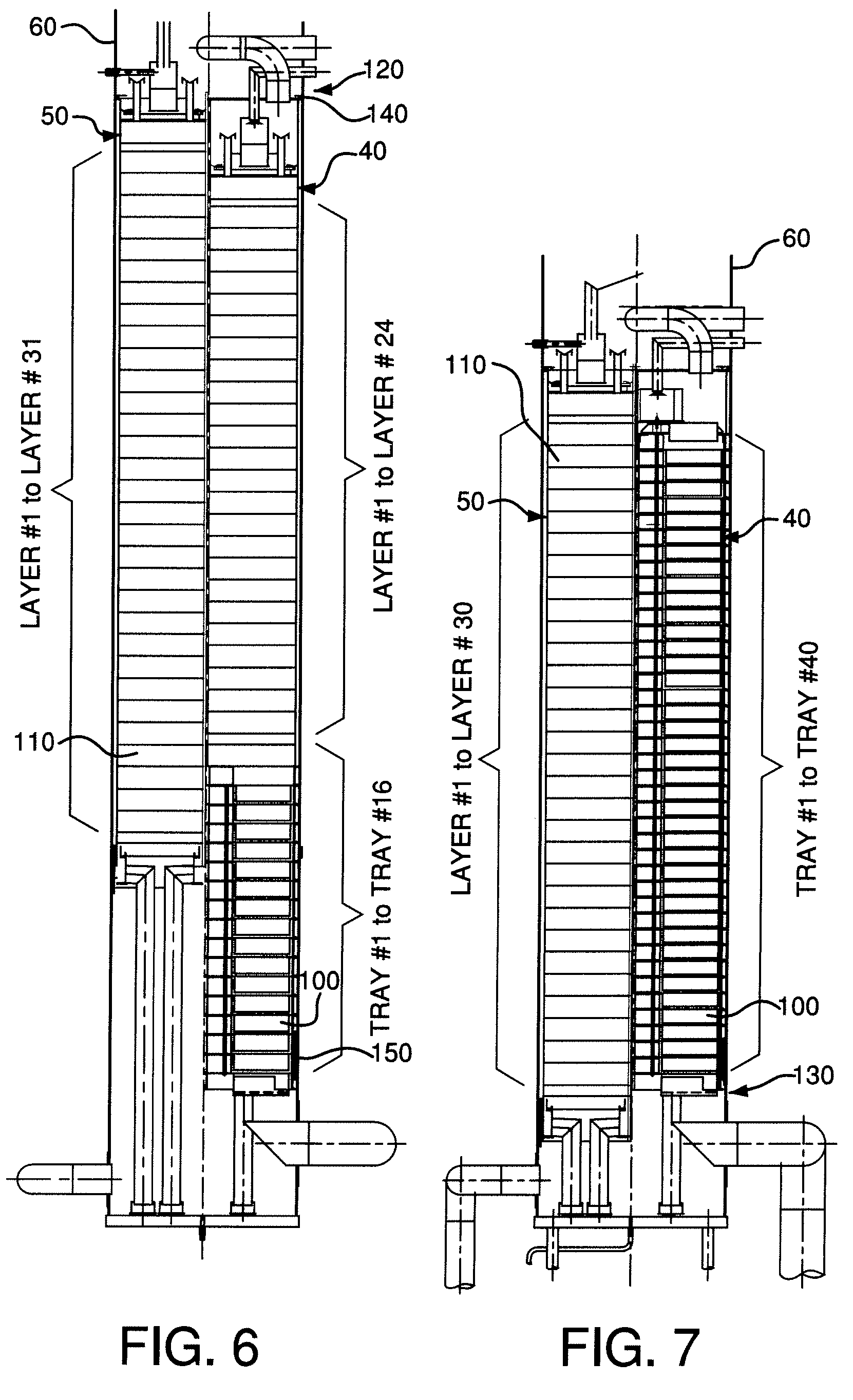
[0036]FIG. 2 illustrates an embodiment of present invention where separate preformed divided wall columns 40, 50 may be constructed for use in a shell column 60. The shell column 60 may be pressurized, for example. The shell column 60 may also be under vacuum conditions, for example. The diameter of the shell column 60 may vary. For example, the diameter of the shell column 60 may be designed as a function of the design pressure. The shell column 60 may be cylindrical or substantially cylindrical, for example. The divided wall columns 40, 50 may be semi-cylindrical or substantially semi-cylindrical, for example.

[0037]In FIGS. 3-11, elements that correspond to elements in the previously illustrated embodiments are identified by the same number. As illustrated in FIG. 3, the divided wall columns 70, 80, 90 may also be substantially pie-shaped or substantially sectorial, ...


PUM


Abstract

A divided exchange column includes a shell column having a first longitudinal axis, a cylindrical wall spaced apart from and surrounding the first longitudinal axis and defining a first interior space, a first divided wall column having a second longitudinal axis substantially parallel to the first longitudinal axis, and a second divided wall column having a third longitudinal axis substantially parallel to the first and the second longitudinal axes, where the first divided wall column and the second divided wall column are positioned in the first interior space of the shell column.

Description

BACKGROUND[0001]Traditional methods for building divided wall columns for use in heat and / or mass transfer processes required welding a dividing wall in an appropriate location directly to a pressure shell column and then proceeding with the installation of packing or distillation trays on either side of the divided wall column. Other methods for building divided wall columns required that half-cylindrical shells be welded onto the dividing wall itself. Both methods required a welder, working inside the pressure shell column, to place welds on the interior wall of the column and the dividing wall to prevent leaks between these members.[0002]The previous methods of manufacture and designs of divided wall columns for smaller sized applications, however, are problematic for several reasons.[0003]First, use of a divided wall column incorporating a traditional dividing wall subjects the dividing wall to both pressure and temperature differences on both sides of the divided wall column. T...

Claims


Application Information

Patent Timeline
Patent Type & Authority Patents(United States)
IPC IPC(8): B01D3/10B01D3/14
CPCB01D3/14B01D3/141F25J3/04939F25J3/04921F25J3/04903F25J3/04909F25J2200/96
Inventor KOVAK, KENNETH WILLIAM
Owner AIR PROD & CHEM INC
Why Eureka
Try Eureka