Supercharge Your Innovation With Domain-Expert AI Agents!

Spacer member reducing fretting wear and fastened structures using spacer member

a spacer and fretting technology, applied in the field of spacer members, can solve the problems of difficulty in judging the progress of fretting wear, difficulty in judging the degree of fretting wear, and low fretting wear effect, so as to reduce the occurrence of wear and reduce the occurrence of abrasion

Inactive Publication Date: 2013-07-09
IMOTT INC
View PDF16 Cites 0 Cited by
  • Summary
  • Abstract
  • Description
  • Claims
  • Application Information

AI Technical Summary

Benefits of technology

The spacer member significantly reduces abrasion and wear on contact surfaces, maintaining the fastening force and preventing fatigue fracture, while being resistant to rust and capable of returning to its original shape after bending, thus extending the lifespan of tire wheels, hubs, and brake drums.

Problems solved by technology

This fretting wear indicates the wear when sliding or vibrating surfaces of fastened parts of a structures abrade due to fine vibration of the sliding or vibrating surfaces of the structures in the state where the sliding or vibrating surfaces of the structures continuously receive fine vibration while receiving pressure.
Therefore, it is difficult to judge the state of advance of this fretting wear from the appearance of these structures.
Further, due to the differences in the environments in which the fastened parts of these structures are placed, the degree of wear of the fretting wear often differs.
Usually, fastened parts of structures are retightened based on the state of use of the structures, but fretting wear has little effect.
Depending on the state of advance of fretting wear of structures, this leads to the structures themselves fracturing.
Furthermore, it is known that when members of structures receive fine vibration, regardless of whether the direction of this sliding or vibration is a direction parallel to or vertical to the sliding or vibrating surfaces or a composite of the same, wear occurs particularly easily inside the fastening force lines (the range affected by the force fastening the head of a bolt with the nut represented by the lines).
Such aluminum tire wheels oxidize at their surfaces resulting in the formation of oxide film.
When such aluminum tire wheels and hubs are fastened, fretting wear occurs.
As a result, the tire wheels become thinner leading to fatigue fracture.

Method used


Image

  • Spacer member reducing fretting wear and fastened structures using spacer member
  • Spacer member reducing fretting wear and fastened structures using spacer member
  • Spacer member reducing fretting wear and fastened structures using spacer member

Examples


example 1

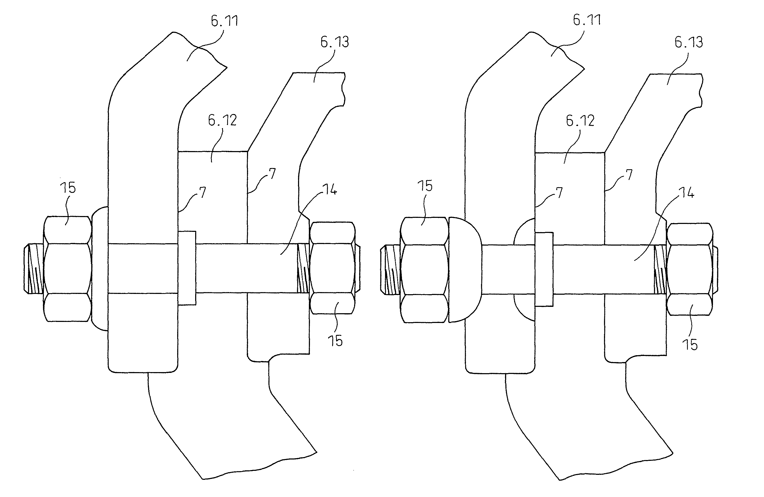
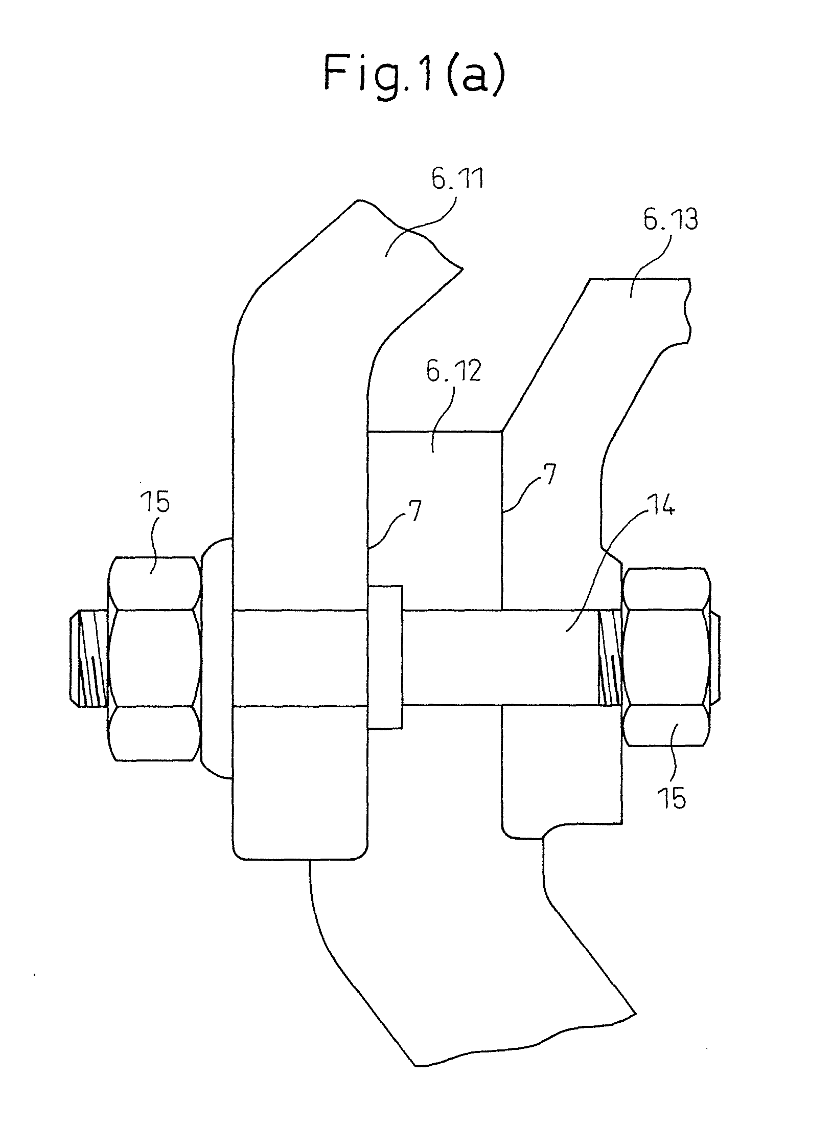
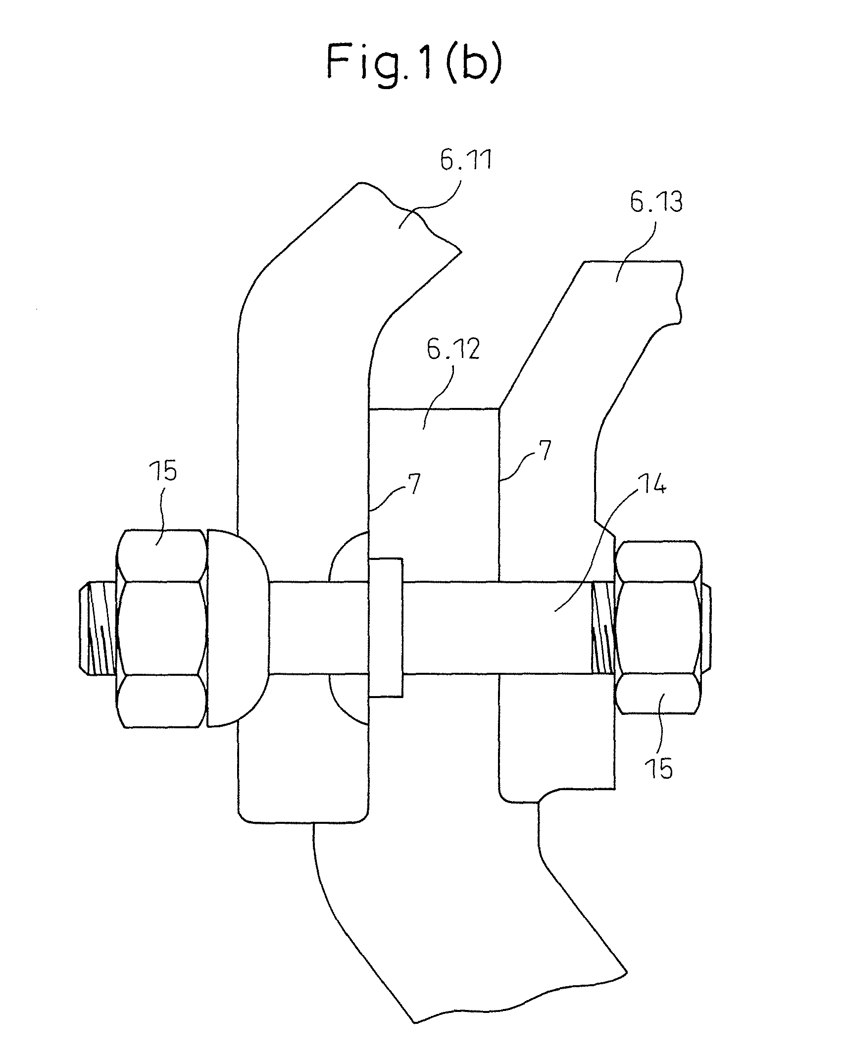
[0052]When the automobile engine is started, the engine generates a rotational force. A large torque is applied from the engine to the drive parts and rotational force is transmitted to the coupled drive parts (for example, tire wheels, hubs, and brake drums). The tire wheels, hubs, and brake drums are fastened by bolts and nuts to be able to turn and slide. Therefore, the tire wheels, hubs, and brake drums are abraded around the fastened parts of the bolts and nuts (hatched parts 23 of ISO type of FIG. 3(a) and JIS type of FIG. 3(b)). Due to the abrasion of this peripheral part, first the fastened surfaces are worn, the fastening axial force falls, then the bolts loosen and fracture.

[0053]That is, in consideration of the prior art, by experience, the bolt strength is used for design of power transmission, but the surfaces where fretting wear occurs (hatched parts 23 of hub of ISO type of FIG. 3(a) and JIS type of FIG. 3(b)) become uneven, the fastening force falls (bolts and nuts l...

example 2

[0054]As another example, when a bearing part in which bearings are press fit and a shaft runs through the center of the bearings etc. is subjected to fine vibration at the shaft of the bearing part in other than the rotational and sliding directions, the balls inside the bearing abrade the inside surface of the outer race or the outer periphery rubs against the surface of the hole and the hole is enlarged and balls fall out or fine stripes of fine wear are formed and detachment occurs. In addition, various wear occurs. In these cases as well, by inserting the spacer member of the present invention for the purpose of reducing abrasion, it is possible to reduce the effects on the members.

example 3

[0055]Structures of aluminum parts (die castings, machined parts, welded structures, etc.) and different metals (iron, copper, stainless steel, cast iron, etc.) placed face to face and fastened by bolts and nuts etc. have been increasing. Recently, passenger cars with bodies made of all aluminum or a chassis made of iron and the top part, trunk hood, engine hood, etc. made of aluminum have appeared. In such a case, the spacer member of the present invention may be inserted between the iron and aluminum for aluminum protection. The effect of reducing the wear of aluminum due to the fine vibration applied to the body without the fastening force being reduced can be expected thereby leading to an improvement in safety. Further, a DLC film is low in electrical conductivity, so the effect of reducing so-called galvanic corrosion can also be anticipated.


PUM

PropertyMeasurementUnit
widthaaaaaaaaaa
thicknessaaaaaaaaaa
thicknessaaaaaaaaaa

Abstract

The present invention relates to a spacer member reducing fretting wear and fastened structures using a spacer member, furthermore, the present invention provides a spacer member 1 sandwiched between contact surfaces 7 of contact materials 6 subject to abrasion and suffering from wear and provided with sliding and vibrating surfaces 2, 2 characterized in that the sliding or vibrating surfaces (2, 2) of the spacer member 1 have a higher hardness than at least one of the contact surfaces (7) of the first contact material (6) and the second contact material (6′) and the sliding or vibrating surfaces (2, 2) of the spacer member 1 have a lower coefficient of friction and a higher flatness than at least one of the contact surfaces (7) of the first contact material (6) and the second contact material (6′), whereby the sliding or vibrating surfaces 2, 2 of the spacer member 1 do not easily wear down the contact surfaces 7 of the contact materials 6.

Description

CROSS-REFERENCE TO RELATED APPLICATION(S)[0001]This application is a National Phase Patent Application and claims the priority of International Application Number PCT / JP2008 / 059958, filed on May 23, 2008, which claims priority of Japanese Patent Application Number 2007-272829, filed on Oct. 19, 2007.TECHNICAL FIELD[0002]The present invention relates to a spacer member for reducing fretting wear and fastened structures using a spacer member. Furthermore, specifically the present invention relates to a spacer member reducing abrasion at one structure or both structures occurring due to rubbing when component structures slide or vibrate with respect to each other. Further, the present invention relates to fastened structures using a spacer member at the sliding and vibrating surfaces of the structures.BACKGROUND ART[0003]Fretting wear is one type of wear. This fretting wear indicates the wear when sliding or vibrating surfaces of fastened parts of a structures abrade due to fine vibrat...

Claims


Application Information

Patent Timeline
Patent Type & Authority Patents(United States)
IPC IPC(8): F16C33/16
CPCB60B27/00F16B35/042F16B5/02
Inventor OOTAKE, NAOTOMATSUO
Owner IMOTT INC
Features
  • R&D
  • Intellectual Property
  • Life Sciences
  • Materials
  • Tech Scout
  • Unparalleled Data Quality
  • Higher Quality Content
  • 60% Fewer Hallucinations
Learn More