Display, method for producing display, and electronic apparatus

a technology for electronic equipment and displays, applied in the direction of discharge tubes/lamp details, discharge tubes luminescnet screens, transportation and packaging, etc., can solve the problems of difficult to provide a sufficient sealing effect, and gas outside the display is liable to enter the display region, so as to improve the reliability of the display

Active Publication Date: 2013-07-09
JOLED INC
View PDF15 Cites 8 Cited by
  • Summary
  • Abstract
  • Description
  • Claims
  • Application Information

AI Technical Summary

Benefits of technology

[0007]It is desirable to provide a display which is capable of sufficiently preventing the permeation of a gas outside the display into a display region including elements and performing display with high reliability, and a method for producing the display.
[0010]In the display having the structure described above, the distance of the gap between the first substrate and the peripheral projection of the second substrate over the entire perimeter is smaller than the distance between the first substrate and the second substrate in the display region. Furthermore, the second sealing layer is arranged in the narrow gap over the entire perimeter. Thus, a portion where the second sealing layer is exposed to the outside is minimized, preventing the permeation of external gases (water vapor and oxygen) into the first sealing layer through the second sealing layer.
[0012]In the production method described above, the material for the second sealing layer that has been fed around the first sealing layer is filled into the whole region between the peripheral projection and the first substrate by capillary action. Thereby, the display having the foregoing structure is produced while the second sealing layer does not protrude from the gap between the first substrate and the second substrate, so that the area of the second sealing layer exposed to the outside is minimized.
[0013]As described above, according to an embodiment of the present invention, a portion where the second sealing layer arranged around the first sealing layer is exposed to the outside is minimized, thereby preventing the permeation of external gases (water vapor and oxygen) into the first sealing layer through the second sealing layer and the deterioration of the elements covered with the first sealing layer. It is thus possible to improve the reliability of a display and an electronic apparatus each of which includes panels in which elements are sealed between a first substrate and a second substrate.

Problems solved by technology

Thus, a gas outside the display is liable to enter the display region through the adhesive layer.
It is therefore difficult to provide a sufficient sealing effect.

Method used


Image

  • Display, method for producing display, and electronic apparatus
  • Display, method for producing display, and electronic apparatus
  • Display, method for producing display, and electronic apparatus

Examples


first embodiment

1. First Embodiment

Structure of Display

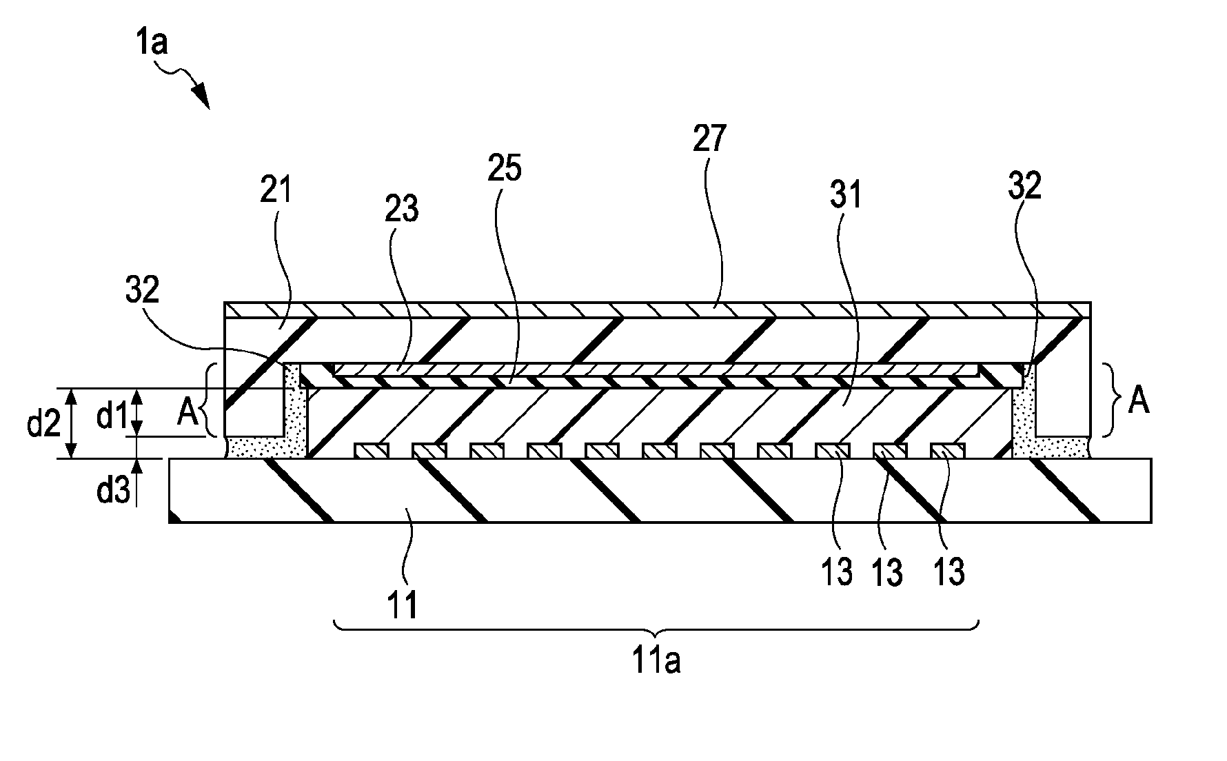
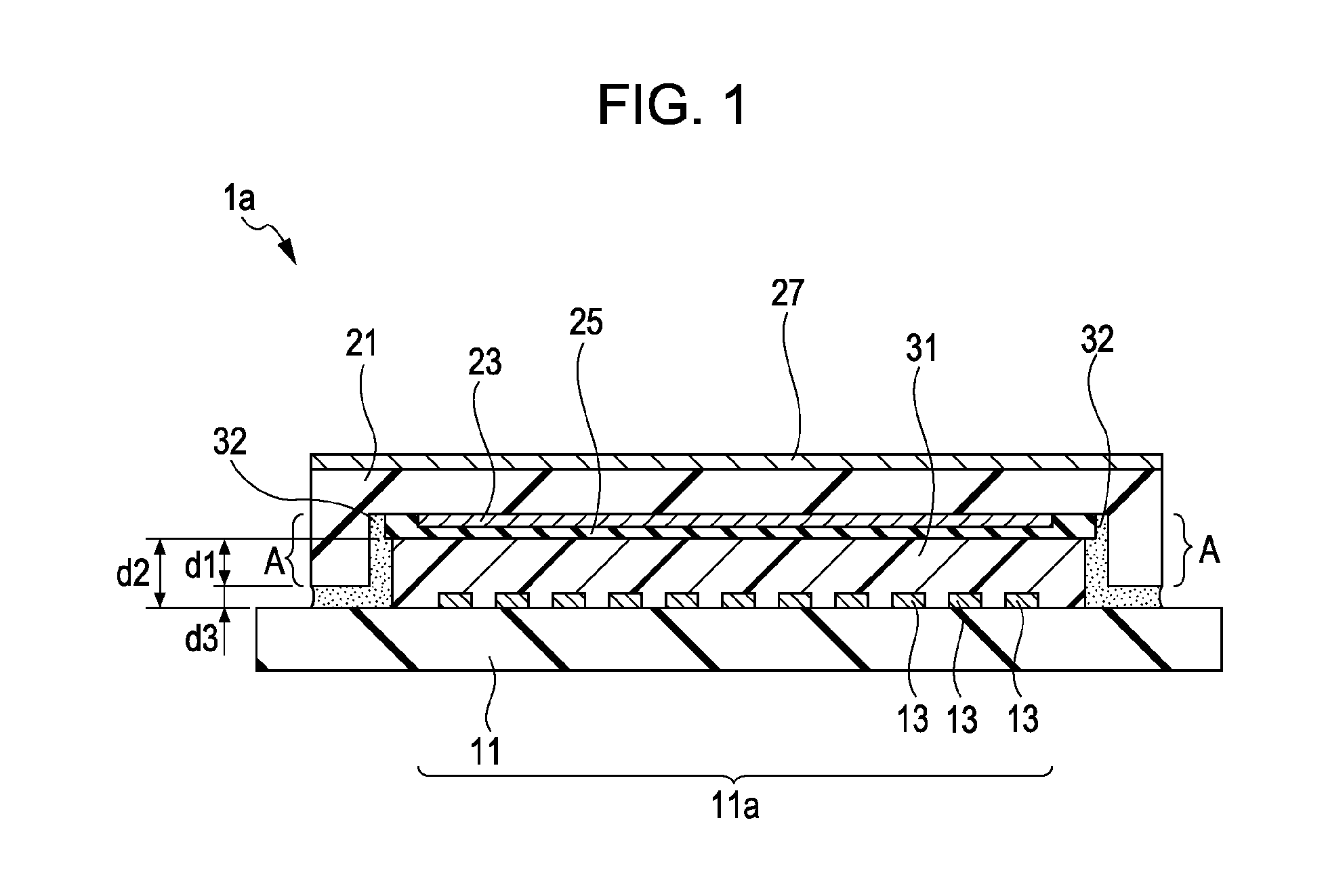
[0026]FIG. 1 is a schematic cross-sectional view illustrating the structure of a display 1a according to a first embodiment. An example of the display 1a shown in this figure is a display including organic electroluminescent elements and has the structure described below.

[0027]A plurality of light-emitting elements are arrayed in a wide display region 11a arranged in the middle of a first substrate 11. A second substrate 21 is arranged so as to face a side of the first substrate 11 on which light-emitting elements 13 are arranged. A first sealing layer 31 is formed between the first substrate 11 and the second substrate 21 so as to cover the display region 11a including the light-emitting elements 13. Furthermore, a second sealing layer 32 is formed so as to surround the first sealing layer 31. In particular, in the first embodiment, the entire periphery of the second substrate 21 is provided with a peripheral projection A extending toward the ...

second embodiment

2. Second Embodiment

Structure of Display

[0047]FIG. 3 is a schematic cross-sectional view illustrating a display 1b according to a second embodiment. The display 1b shown in this figure has the same structure as the display 1a according to the first embodiment, except that the peripheral projection A arranged on the second substrate 21 is separately formed on a flat portion 21a of the second substrate 21.

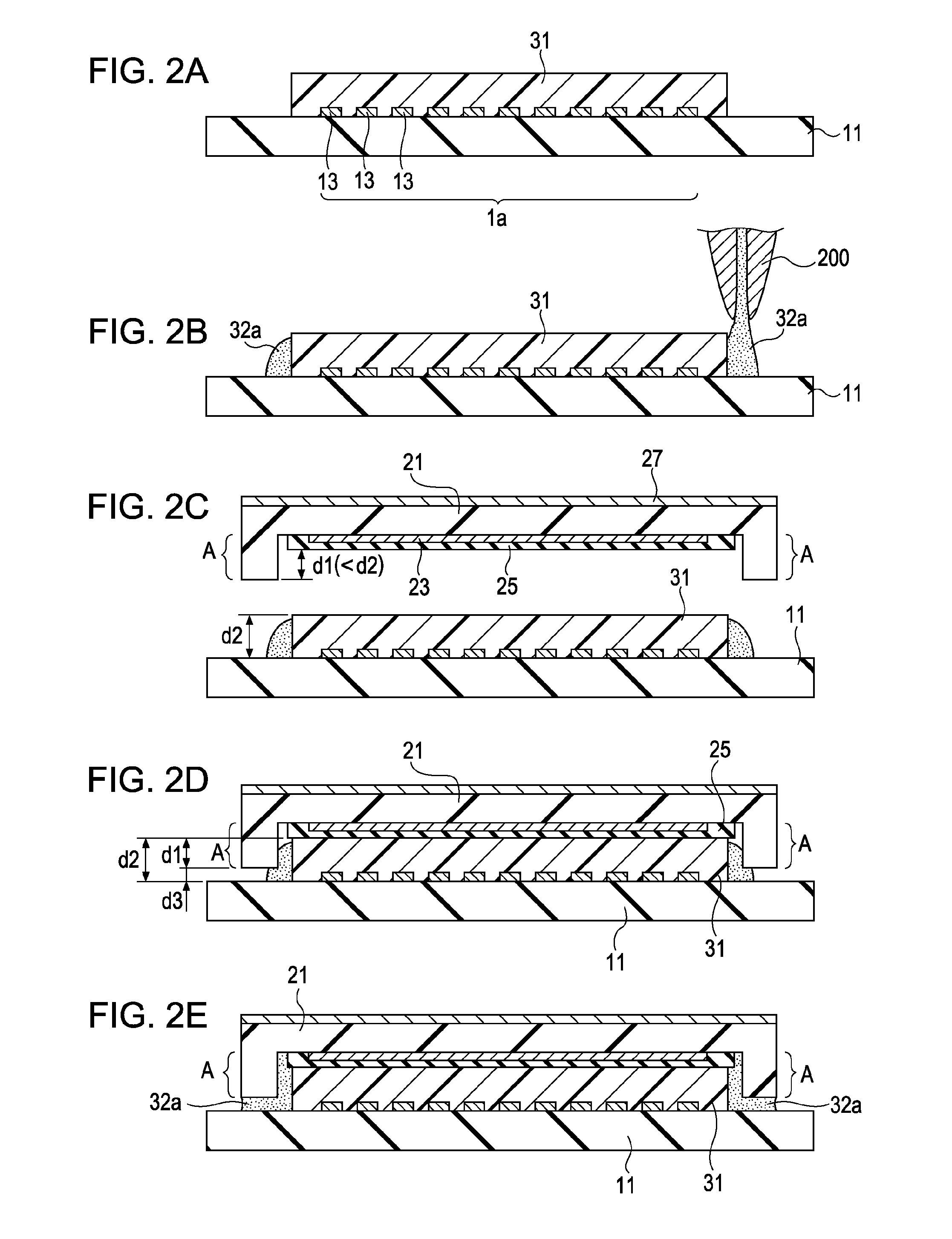
[0048]In this case, the peripheral projection A is composed of, for example, an epoxy resin. The height of the peripheral projection A composed of the epoxy resin is the same as in the first embodiment. That is, the height d1, including the thickness of the inorganic protective film 25, of the peripheral projection A is slightly smaller than the height (thickness) d2 of the first sealing layer 31. Thus, the peripheral projection A is apart from the first substrate 11 by a distance d3. The distance d3 is a distance such that a gap between the first substrate 11 and the peripheral proj...

third embodiment

3. Third Embodiment

[0057]FIGS. 4 to 8G show examples of electronic apparatuses including display panels formed of the displays according to an embodiment of the present invention described above. The display according to an embodiment of the present invention is applicable to display units of electronic apparatuses, in all fields, that display video signals fed thereinto or produced therein. Examples of the electronic apparatuses to which an embodiment of the present invention is applied will be described below.

[0058]FIG. 4 is a perspective view of a television set to which an embodiment of the present invention is applied. The television set according to this application example includes a display screen unit 101 having a front panel 102, and a filter glass 103. The display according to an embodiment of the present invention is used as the display screen unit 101.

[0059]FIGS. 5A and 5B show a digital camera to which an embodiment of the present invention is applied. FIG. 5A is a per...


PUM


Abstract

A display includes a first substrate including elements arranged on a main surface of the first substrate, a second substrate arranged so as to face the main surface of the first substrate on which the elements are arranged, a first sealing layer arranged between the first substrate and the second substrate so as to cover the elements, and a second sealing layer arranged between the first substrate and the second substrate so as to surround the first sealing layer. The second substrate has a peripheral projection, the entirety of which projects toward the side on which the elements are arranged, and the peripheral projection surrounds the first sealing layer. The second sealing layer is arranged between the first substrate and the second substrate so as to extend from the periphery of the first sealing layer to the peripheral projection.

Description

BACKGROUND OF THE INVENTION[0001]1. Field of the Invention[0002]The present invention relates to a display, a method for producing a display, and an electronic apparatus, and more specifically, to a display including a light-emitting element sealed between two substrates, a method for producing the display, and an electronic apparatus including the display.[0003]2. Description of the Related Art[0004]In displays including arrayed organic electroluminescent elements, the organic electroluminescent elements are extremely sensitive to water and oxygen and degraded by gases (e.g., water vapor and oxygen) that permeating from the outside, easily causing defects such as nonluminous areas (dark spots) and a reduction in luminance. Accordingly, it is important to employ a sealing technique to prevent the permeation of gases.[0005]Currently, a sealing structure is used in which light-emitting elements arranged on a first substrate are covered with a protective film, and a second substrate is...

Claims


Application Information

Patent Timeline
Patent Type & Authority Patents(United States)
IPC IPC(8): H01L51/50
CPCH01L51/5237H05B33/10H05B33/04H01L27/322Y10T428/24612H10K59/38H10K50/841H10K50/8426H10K50/844H10K50/84
Inventor MORIWAKI, TOSHIKI
Owner JOLED INC
Why Eureka
Try Eureka