Method and system for charging an auxilary battery in a plug-in electric vehicle

a technology of electric vehicles and auxilary batteries, which is applied in the direction of battery/fuel cell control arrangement, hybrid vehicles, secondary cell servicing/maintenance, etc., can solve the problems of reducing the driving range and overall efficiency of the hev, reducing the electric charge in the secondary battery, and reducing the soc of the battery. , to achieve the effect of reducing the energy used in the onboard charging system

Active Publication Date: 2013-07-09
FORD GLOBAL TECH LLC
View PDF10 Cites 109 Cited by
  • Summary
  • Abstract
  • Description
  • Claims
  • Application Information

AI Technical Summary

Benefits of technology

[0007]An upper charge level may be determined. The upper charge level may be approximately an upper level of the predetermined operating range of charge levels. Alternatively, the upper charge level may be greater than the predetermined operating range of charge levels. The upper charge level may be a charge level between 12 volts and 15 volts. Furthermore, the upper charge level may be a predetermined maximum charge of the auxiliary battery. The auxiliary battery is allowed to be charged to the upper charge level using an external power source thereby reducing energy used from an onboard charging system in the vehicle to charge the auxiliary battery during a drive mode of the vehicle.
[0009]The method includes charging the auxiliary battery to the upper charge level using the external power source thereby reducing energy used from the onboard charging system. The method may include determining parameters of the auxiliary battery to obtain the predetermined operating range of charge levels.

Problems solved by technology

However, the SOC of the battery decreases when the high-voltage storage battery provides electric power for the vehicle.
However, the amount of electric charge in the secondary battery decreases when driving various loads in the HEV.
However, using stored onboard energy to recharge the secondary battery can reduce the driving range and overall efficiency of the HEV.

Method used


Image

  • Method and system for charging an auxilary battery in a plug-in electric vehicle
  • Method and system for charging an auxilary battery in a plug-in electric vehicle
  • Method and system for charging an auxilary battery in a plug-in electric vehicle

Examples


Embodiment Construction

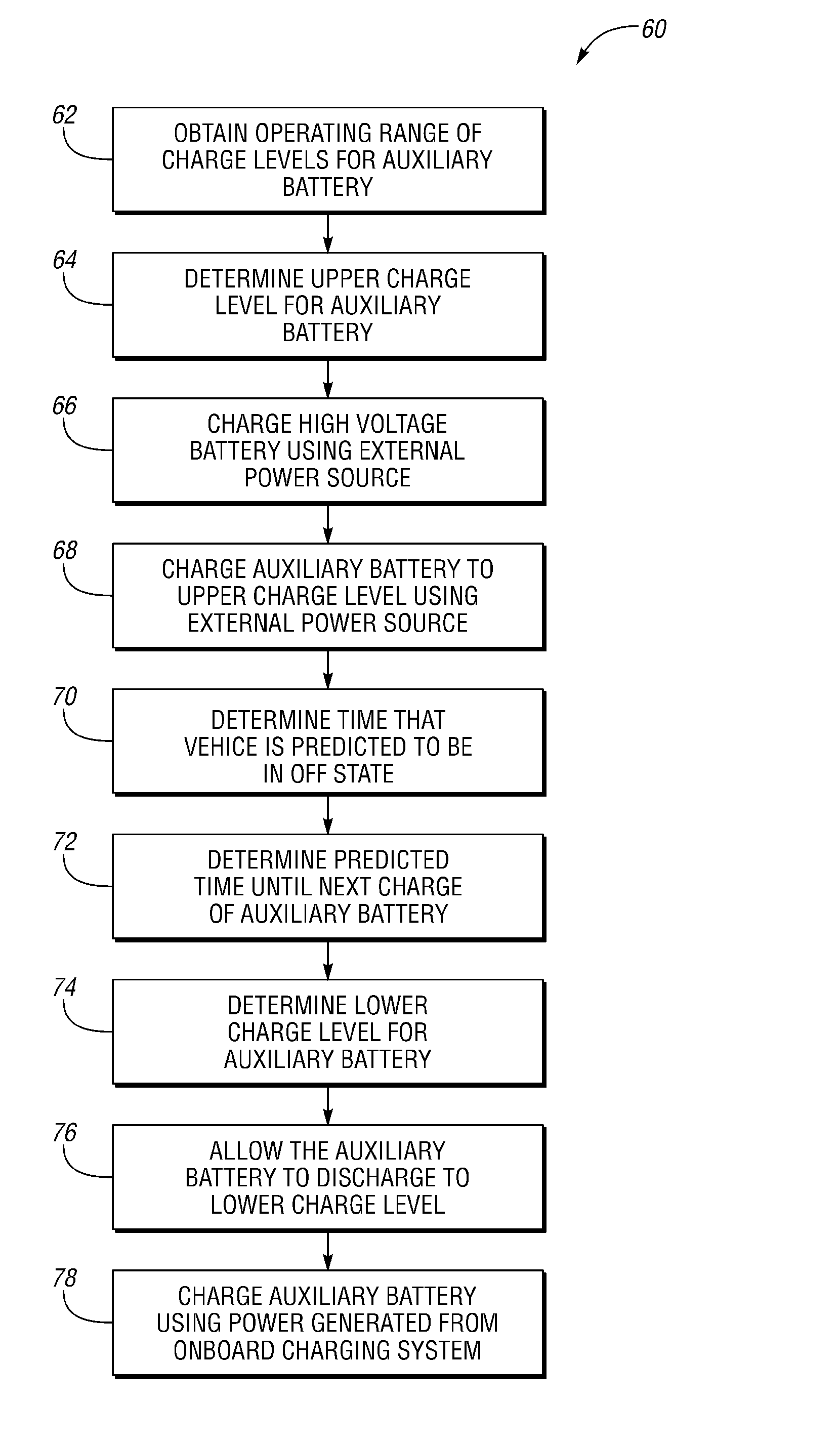
[0018]Embodiments of the present disclosure generally provide a method and system for charging an auxiliary battery in a plug-in electric vehicle using an external power source.

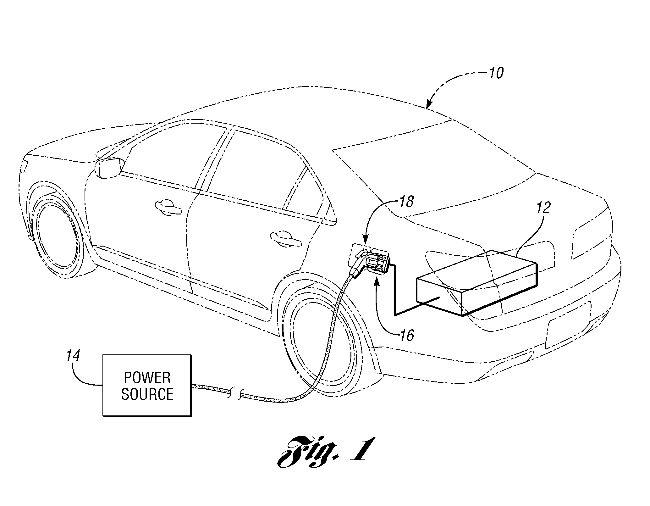
[0019]With reference to FIG. 1, a plug-in electric vehicle 10 (hereinafter “vehicle”) is provided. The vehicle 10 may be any type of electric vehicle that can be plugged into a power source 14 that is external to the vehicle 10 (hereinafter “external power source”), such as a plug-in electric vehicle, a plug-in hybrid electric vehicle (PHEV), a battery electric vehicle (BEV), a pure electric vehicle, etc. The plug-in vehicle 10 of FIG. 1 includes an onboard charging system 12. It should be understood that the term “plug-in vehicle” includes any type of automotive vehicle that can connect to the external power source 14 to receive electric power from the external power source 14. Thus, for example, the vehicle 10 may be a vehicle that includes a charge port 16 to receive a charge plug 18 and to transfer electr...


PUM


Abstract

A system and method is provided for charging an auxiliary battery in a plug-in electric vehicle with an onboard charging system. The auxiliary battery has a predetermined operating range of charge levels. The auxiliary battery is charged to an upper charge level using an external power source thereby reducing energy used from the onboard charging system to charge the auxiliary battery during a drive mode of the vehicle. The upper charge level may be substantially similar to an upper level of the predetermined operating range of charge levels or greater than the predetermined operating range of charge levels. The auxiliary battery may be allowed to discharge to a lower charge level, which may be substantially similar to a lower level of the predetermined operating range of charge levels or less than the predetermined operating range of charge levels.

Description

BACKGROUND[0001]1. Technical Field[0002]Charging an auxiliary battery in a plug-in electric vehicle using a power supply external to the vehicle.[0003]2. Background Art[0004]A hybrid electric vehicle (HEV) generally includes a high-voltage storage battery, a secondary battery, a combustion engine, and an electric motor. The high-voltage storage battery has a state of charge (SOC). However, the SOC of the battery decreases when the high-voltage storage battery provides electric power for the vehicle. For example, the SOC of the high-voltage storage battery decreases when providing electric power to the electric motor to drive traction wheels on the vehicle. In such an example, the electric power stored in the high-voltage storage battery decreases and the electric-only driving range of the HEV is reduced.[0005]The secondary or auxiliary battery operates at a lower voltage than the high-voltage storage battery, such as 12-volts. The secondary battery can provide electric power to driv...

Claims


Application Information

Patent Timeline
Patent Type & Authority Patents(United States)
IPC IPC(8): H02J7/00
CPCB60L11/1862H01M10/44H02J7/0022Y02T10/7044Y02T10/92Y02T10/705Y02T90/14Y02T10/7055Y02T10/7005B60L58/13Y02T10/70Y02E60/10H02J7/0013
Inventor CROMBEZ, DALE SCOTT
Owner FORD GLOBAL TECH LLC
Why Eureka
Try Eureka