Liquid crystal display panel

a liquid crystal display panel and display panel technology, applied in the field can solve the problems of significantly increasing the probability of manufacturers misjudging such liquid crystal display panels as defective, and affecting the quality of liquid crystal display panels

Active Publication Date: 2013-07-09
AU OPTRONICS CORP
View PDF13 Cites 3 Cited by
  • Summary
  • Abstract
  • Description
  • Claims
  • Application Information

AI Technical Summary

Benefits of technology

[0011]According to the above description, by disposing the adjustment thin-film transistors and the adjustment lines, the liquid crystal display panel disclosed in this invention can prevent band muras from forming on conventional liquid crystal display panels during the testing periods.

Problems solved by technology

However, because the density and locations of the thin-film transistors in the liquid crystal display panel are not consistent across the panel, variations in the thin-film transistors may arise due to the loading effect during the manufacturing process.
This causes a significantly increased probability of the manufacturers misjudging such liquid crystal display panels as defective due to the band mura during the test period.

Method used


Image

  • Liquid crystal display panel
  • Liquid crystal display panel
  • Liquid crystal display panel

Examples


Embodiment Construction

[0017]In the following description, this invention will be explained with reference to embodiments thereof. This invention provides a liquid crystal display panel. However, the description of these embodiments is only for purposes of illustration rather than limitation. It should be appreciated that in the following embodiments and the attached drawings, elements unrelated to this invention are omitted from depiction; and the dimensional relationships among individual elements in the attached drawings are illustrated only for ease of understanding, but not to limit the actual scale.

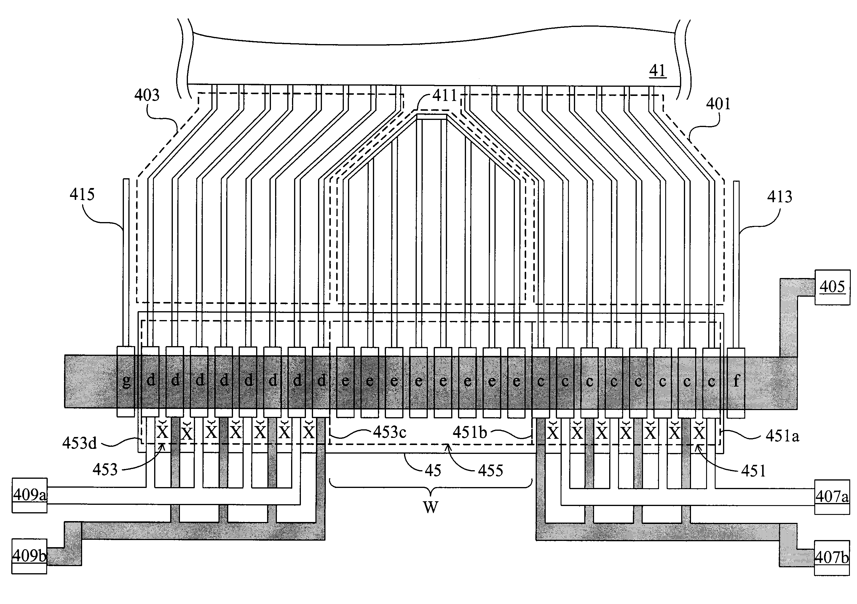
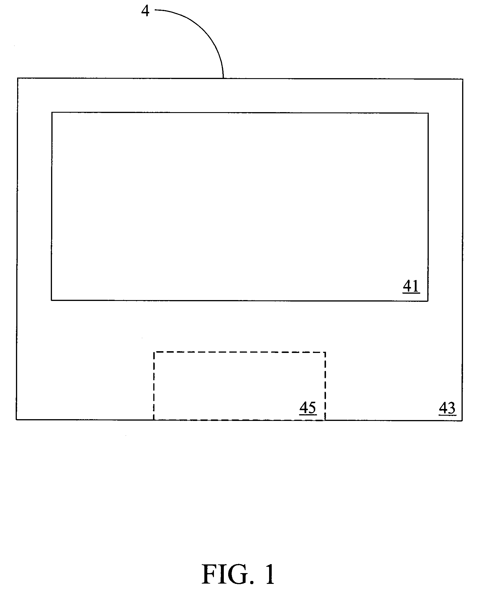
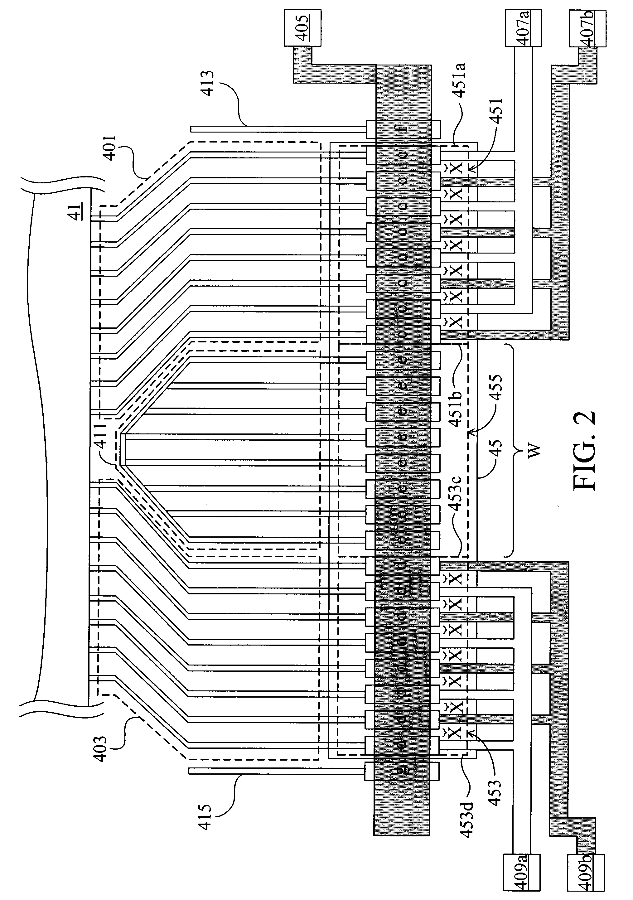
[0018]FIG. 1 is a schematic view of a liquid crystal display panel 4. The liquid crystal display panel 4 comprises a display region 41, a periphery circuit region 43 and a joint obligate region 45. The display region 41 is the region where the liquid crystal display panel 4 displays an image. The periphery circuit region 43 is situated at a periphery of the display region 41. The joint obligate region 45,...


PUM


Abstract

A liquid crystal display panel includes a display region, a periphery circuit region, a joint obligate region, a plurality of first test thin-film transistors (TFTs), a plurality of second TFTs, a plurality of first lines, a plurality of second lines, a blank region, and at least one first adjustment TFT. The first and second test TFTs are disposed on the joint obligate region according to a regular distance. Each of the first and second test TFTs has a transistor width. The first adjustment TFT is disposed on the blank region. The width of the blank region is not smaller than the sum of the twice regular distance and the transistor width. Thereby, the present invention can prevent the band mura of the liquid crystal display panel effectively when the liquid crystal display panel is in testing.

Description

[0001]This application claims the benefit from the priority of Taiwan Patent Application No. 097143184 filed on Nov. 7, 2008, the disclosure of which are incorporated by reference herein in their entirety.CROSS-REFERENCES TO RELATED APPLICATIONS[0002]Not applicable.BACKGROUND OF THE INVENTION[0003]1. Field of the Invention[0004]The present invention relates to a liquid crystal display panel. More particularly, the present invention relates to a liquid crystal display panel capable of preventing the formation of a band mura during a test period.[0005]2. Descriptions of the Related Art[0006]Over recent years, flat panel displays have developed rapidly and gradually replaced conventional cathode ray tube (CRT) displays. Among various flat panel displays, liquid crystal displays (LCDs) are renowned as mainstream products. As liquid crystal displays have been more widely used in automobiles and mobile products, the demands for medium- and small-sized panels grow increasingly. At the back...

Claims


Application Information

Patent Timeline
Patent Type & Authority Patents(United States)
IPC IPC(8): G09G3/36
CPCG09G3/006G09G2300/0426G09G2330/04G09G2330/12
Inventor LIN, SHU-HAOCHEN, YING-YINGLAI, CHUN-KAILIN, CHAO-CHENGHSU, YEN-HUA
Owner AU OPTRONICS CORP
Why Eureka
Try Eureka