Tower and method for the assembly of a tower

a technology for towers and structures, applied in the direction of structural elements, building components, building repairs, etc., can solve the problems of limited work, concrete has to be filled into moulds, and requires a very substantial technical arrangemen

Active Publication Date: 2013-07-16
SIEMENS GAMESA RENEWABLE ENERGY AS
View PDF14 Cites 12 Cited by
  • Summary
  • Abstract
  • Description
  • Claims
  • Application Information

AI Technical Summary

Benefits of technology

[0037]In a preferred embodiment the lowest tower module is cast directly onto a foundation-base-plate, so the preparation of a tower plinth is avoided.

Problems solved by technology

This method has the disadvantage that the concrete has to be filled into a mould, which is located at the top of the tower.
Furthermore personnel are required to fill-in in the concrete into the mould at this final-height, so their work is limited by the time of the day, by health-regulations and by safety-requirements due to the height.
This method has the disadvantage that it requires a very substantial technical arrangement, since high pressure is required for large-dimension components in order to push up the tower during casting.
Large pressures at large diameters require very large technical arrangements.
This arrangement has the disadvantage that for a high tower a reliable injection of the slurry needs special precautions.
Furthermore it may be difficult to insert the cables in the channels, particularly for a high tower.
However despite these arrangements the problem remains to insert the post-tension-cables and to inject slurry into the channel for greater tower heights.
This arrangement has the disadvantage that numerous mounting operations are required and that a high number of fasteners are needed.
This leads to the disadvantage that numerous mounting operations are required and that a high number of fasteners are needed.

Method used


Image

  • Tower and method for the assembly of a tower
  • Tower and method for the assembly of a tower
  • Tower and method for the assembly of a tower

Examples


Embodiment Construction

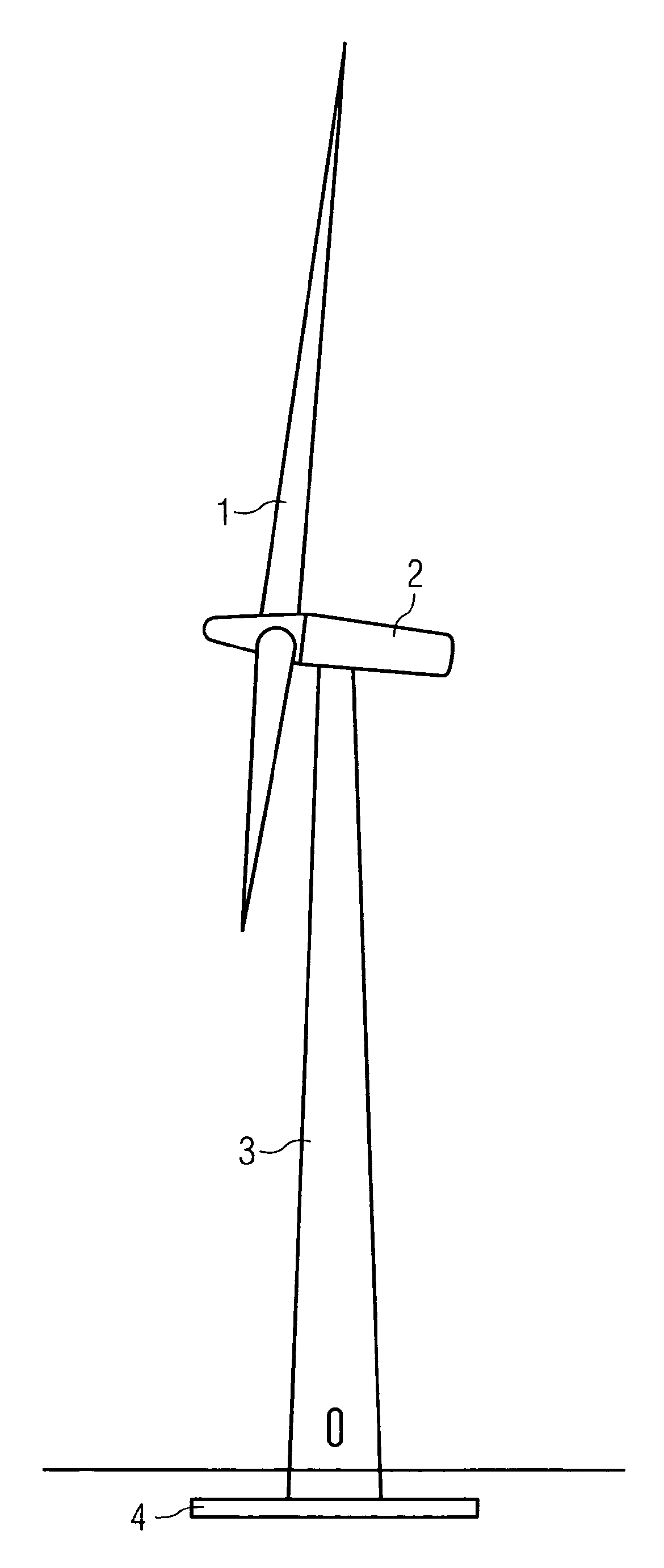
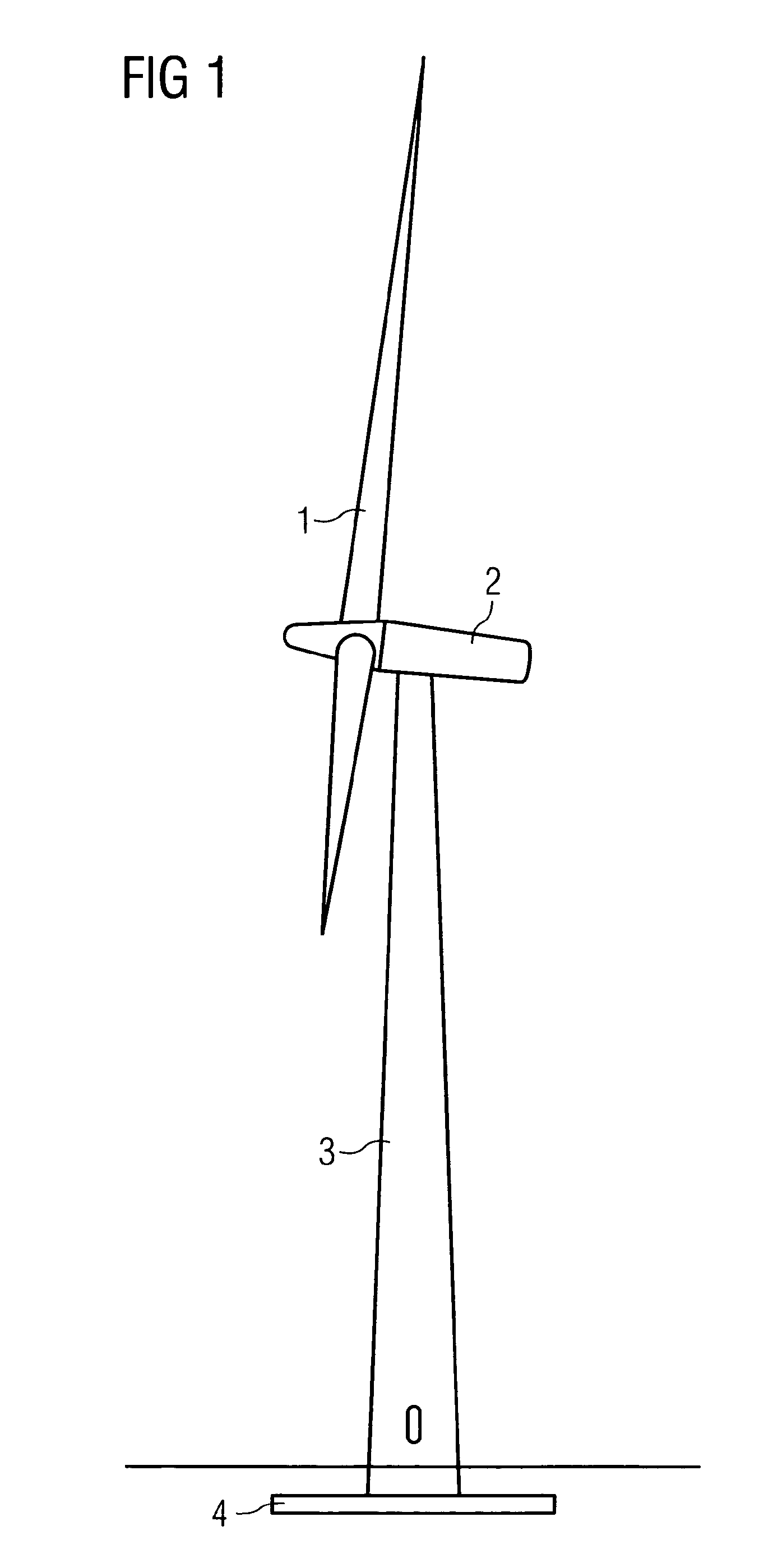
[0048]FIG. 1 shows a wind-turbine using the tower according to the invention. The wind-turbine comprises a rotor 1, which is supported by a nacelle 2. The nacelle 2 is mounted on a tower 3, which is supported by a foundation 4.

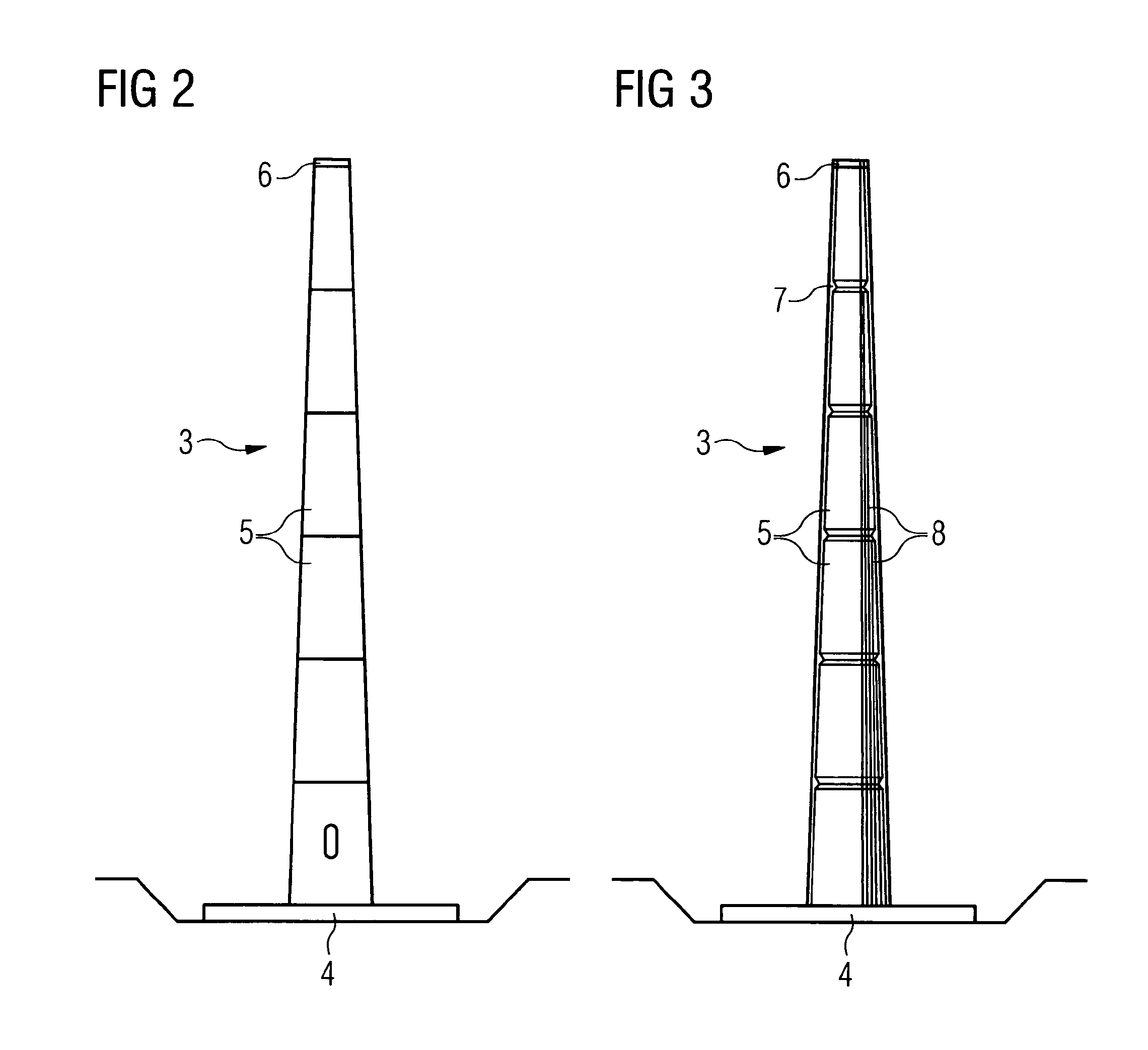
[0049]FIG. 2 shows the concrete tower 3 according to the invention, referring to FIG. 1.

[0050]The concrete tower 3 is constructed with elements as modules 5, which are stacked on top of each other. In a preferred embodiment a last module 6, which is located on top of the tower 3, is substantially shorter than its preceding module 5.

[0051]FIG. 3 shows the tower according to the invention in more detail, referring to FIG. 2.

[0052]In this embodiment each tower module 5 (except the tower module 6 on the top) shows a cable-supporting protrusion 7 at its top.

[0053]On the right side of the tower 3 centerlines of post-tensioning cables 8 are shown. Some of them run through the entire length of the tower 3, from the top module 6 down to the foundation 4, crossing all t...


PUM


Abstract

A number of pre-casted elements are stacked vertically to build the tower, while parts of the elements are forming the tower wall. Each element of the tower is fixed on its position and is connected with a tower foundation by a number of assigned post-tensioned cables. These cables are running inside the tower and they are pulled through the tower without embedding in dedicated channels. The post-tensioned-cables are fixed at certain points with the tower wall via damper-means to prevent their oscillation.

Description

CROSS REFERENCE TO RELATED APPLICATIONS[0001]This application is the US National Stage of International Application No. PCT / EP2008 / 060807, filed Aug. 18, 2008 and claims the benefit thereof. The International Application claims the benefits of U.S. provisional application No. 61 / 080,812 filed Jul. 15, 2008. All of the applications are incorporated by reference herein in their entirety.FIELD OF INVENTION[0002]The invention relates to a method for the assembly of a tower and to the tower. In a preferred embodiment the tower is used for a wind-turbine.BACKGROUND OF INVENTION[0003]Wind-turbines are conventionally mounted on top of steel-towers. The towers consist usually of a number of modules.[0004]As the price of steel is increasing more than the price of concrete it is advantageous to build wind-turbine-towers of concrete.[0005]For large experimental wind-turbines it is known to build and use concrete towers, which are built by using a so called “slip-form pouring method”. One exampl...

Claims


Application Information

Patent Timeline
Patent Type & Authority Patents(United States)
IPC IPC(8): E04H12/00
CPCE04C5/125E04C5/18E04H12/16
Inventor SKJAERBAEK, POULSTIESDAL, HENRIK
Owner SIEMENS GAMESA RENEWABLE ENERGY AS
Why Eureka
Try Eureka