
Thermal loop flow sensor

a flow sensor and thermoelectric loop technology, applied in the direction of volume/mass flow measurement, measurement devices, instruments, etc., can solve the problems of complicated problems, reduce cost, complexity and size, reduce spatial and/or temporal ambient temperature fluctuations, and reduce or eliminate the need for calibration

Active Publication Date: 2013-07-16
WATERS TECH CORP
View PDF11 Cites 6 Cited by
  • Summary
  • Abstract
  • Description
  • Claims
  • Application Information

AI Technical Summary

Benefits of technology

This patent is about a new invention that can reduce the effects of temperature in a tube-based mass-flow sensor. The invention achieves this by providing a common ambient environment upstream and downstream of the tube. This can be done by configuring the tube so that the ends of the upstream and downstream sections have a common temperature. This leads to a reduction in temperature imbalance, which can be caused by heat conduction along the tube. The invention also provides a common heat sink, which further reduces the effects of ambient temperature. The invention is cost-effective and simplifies the construction process of the sensor. It can provide improved sensitivity, automatic compensation for different solvents, and reduced temperature control requirements. Overall, the invention improves the accuracy and reliability of flow sensors.

Problems solved by technology

A correction factor, however, may be unavailable for a particular liquid, or use of a mixture of different liquids can complicate this problem.

Method used


Image

  • Thermal loop flow sensor
  • Thermal loop flow sensor
  • Thermal loop flow sensor

Examples


Embodiment Construction

[0027]The term “nano-flow” herein refers to fluid-flow rates of less than approximately 100 μL / min or, preferably, less than 10 μL / min. Nano-flow rates are useful, for example, in some applications of liquid chromatography performed at pressures of 1,000 psi or greater, and at even higher pressures, such as 5,000 to 10,000 psi or greater.

[0028]Some embodiments of the invention involve apparatus that include both chromatographic and mass-spectrometric components. In some of these embodiments, a chromatographic component is placed in fluid communication with a mass-spectrometric component through use of an appropriate interface, such as an electrospray-ionization interface.

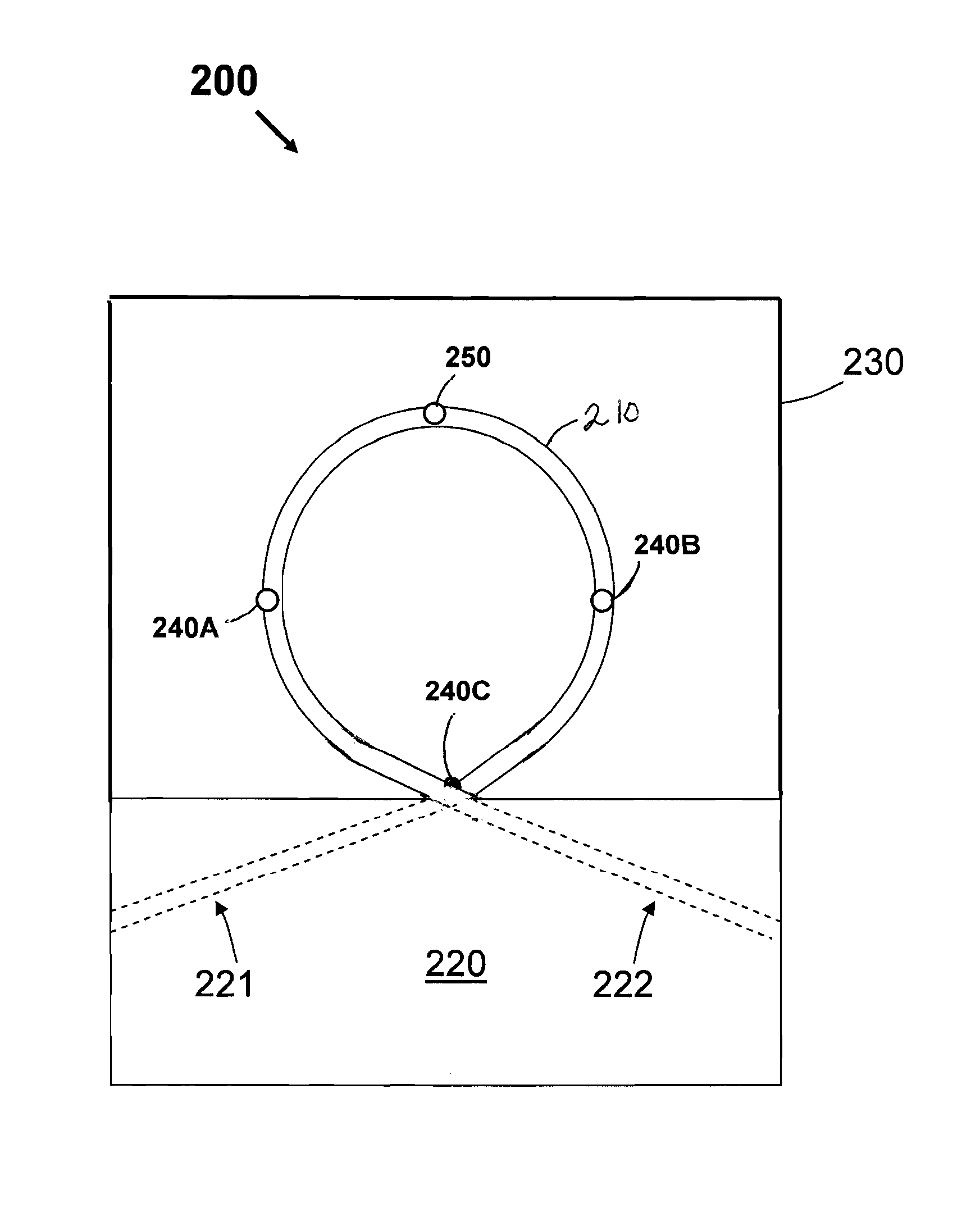
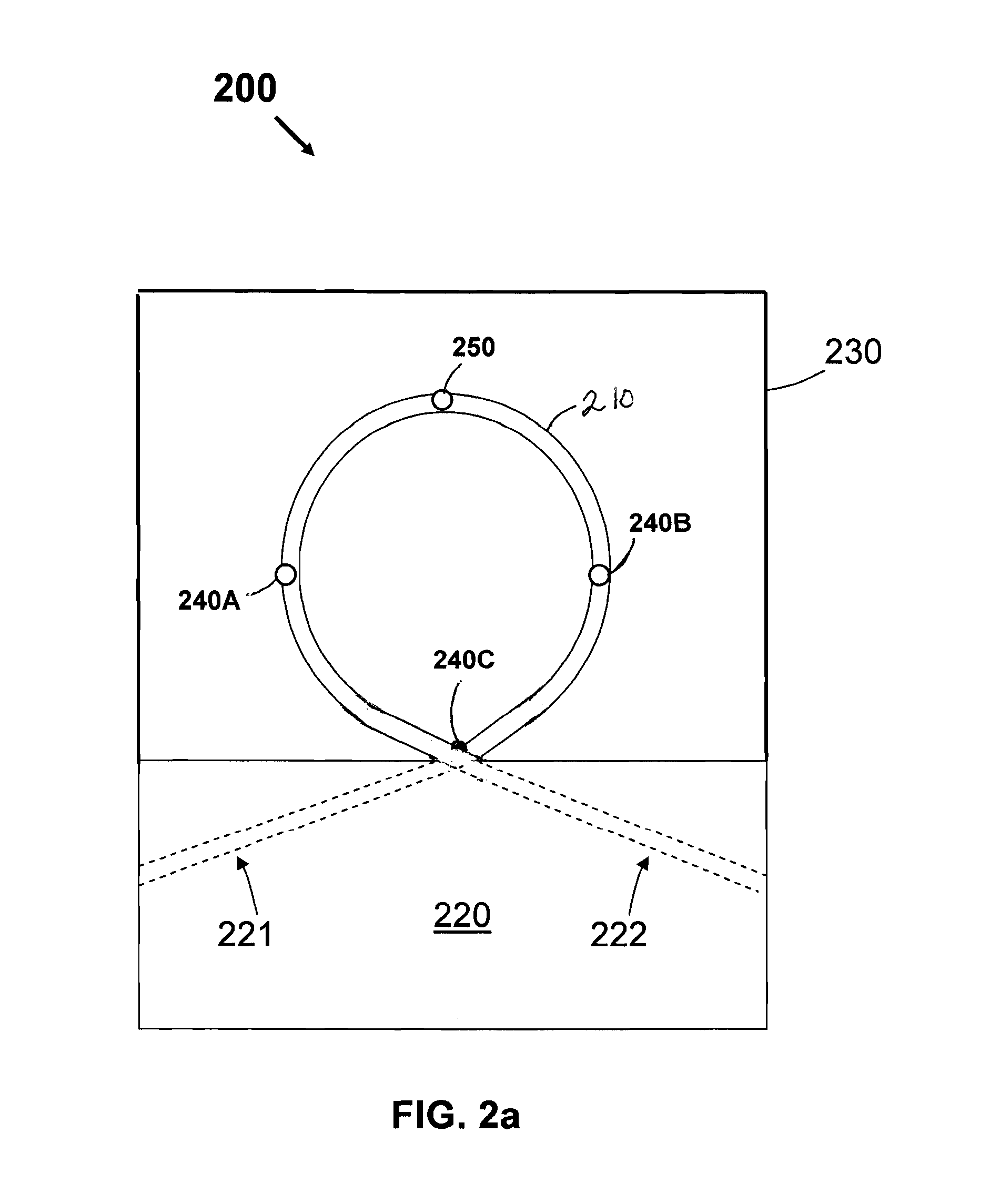
[0029]FIG. 2a is a cross-sectional side-view diagram a flow sensor 200, in accordance with one embodiment of the invention. The flow sensor 200 includes a tube 210 having a loop shape, a substrate 220 in fluidic communication with the tube 210, a heater 250, upstream and downstream temperature sensors 240A, 240B, an...


PUM


Abstract

A flow sensor includes a fluidic component, such as a tube, a heat source, an upstream temperature sensor, and a downstream temperature sensors. The fluidic component defines a flow path having inlet and outlet ends disposed closer to each other than to a mid-point of the flow path. The heat source and the upstream and downstream temperature sensors are disposed in thermal communication with a fluid in the flow path.

Description

CROSS REFERENCE TO RELATED APPLICATIONS[0001]This application claims priority to and benefit of U.S. Provisional Application No. 61 / 021,950, filed Jan. 18, 2008, the entire contents of which are incorporated herein by reference.TECHNICAL FIELD[0002]The invention generally relates to apparatus and methods for fluid flow-rate measurements. More particularly, the invention relates to measurement of flow rates in chromatography apparatus that operate at relatively high pressures and relatively low flow rates.BACKGROUND INFORMATION[0003]Many processes require measurement and control of the flow rate of small amounts of a liquid. Such processes include those employed in the life sciences, chemical analysis (such as liquid chromatography) biotechnology, chemical synthesis and nanotechnology.[0004]Some liquid flow sensors determine a flow rate by utilizing the thermal behavior of a liquid passing through a section of tubing. For example, some nano-flow sensors measure liquid velocity by det...

Claims


Application Information

Patent Timeline
Patent Type & Authority Patents(United States)
IPC IPC(8): G01F1/68
CPCG01F1/6847G01F15/02
Inventor DE CORRAL, JOSE LUIS
Owner WATERS TECH CORP
Learn More