
Impeller housing for percutaneous heart pump

a technology of a percutaneous heart pump and an impeller housing, which is applied in the field of impeller housings for percutaneous heart pumps, can solve the problems of increasing the risk of heart failure patients, so as to reduce the bending of the impeller housing proximal

Active Publication Date: 2013-07-16
PENN STATE RES FOUND +1
View PDF297 Cites 100 Cited by
  • Summary
  • Abstract
  • Description
  • Claims
  • Application Information

AI Technical Summary

Benefits of technology

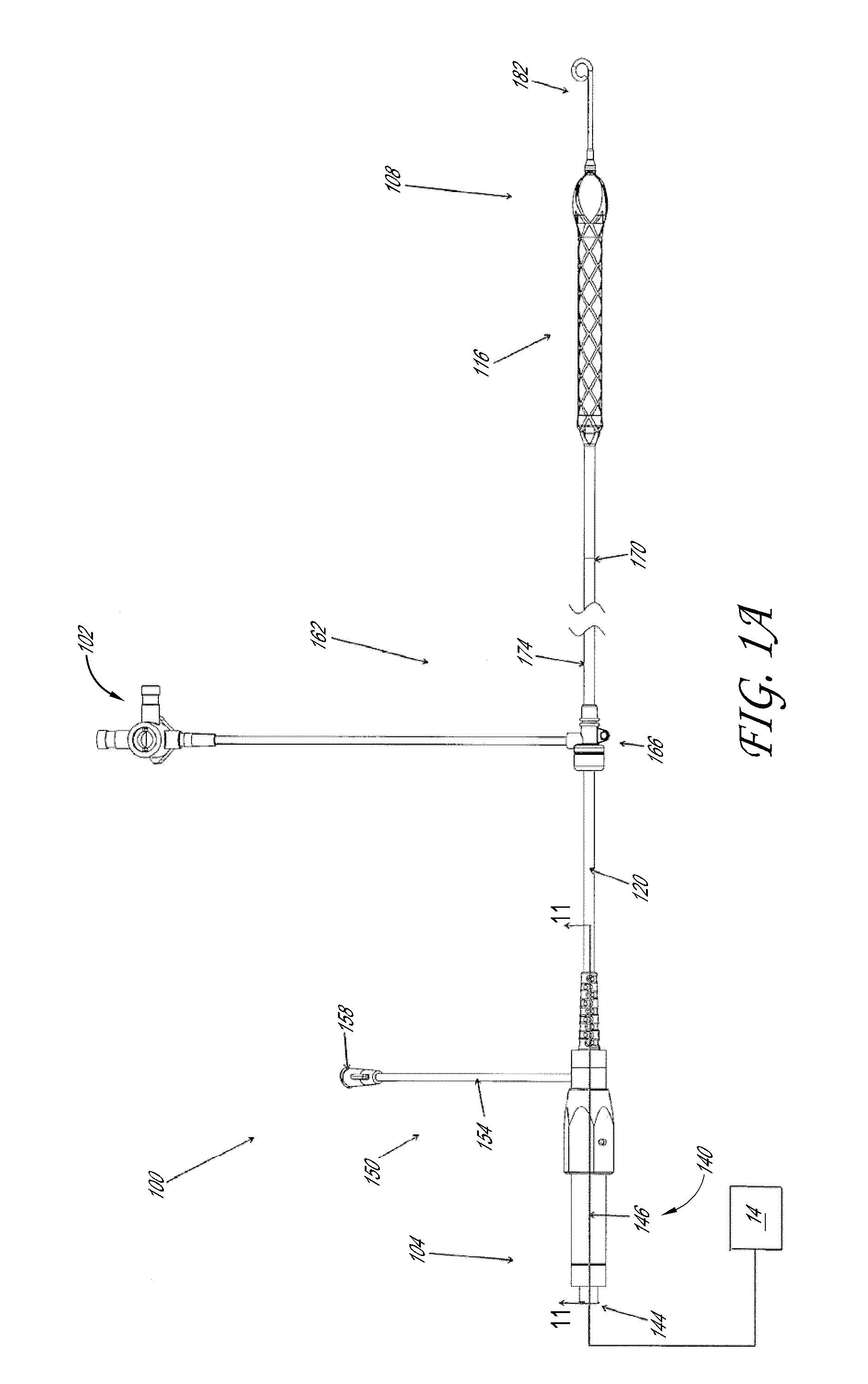
[0008]A catheter assembly for a heart pump is provided that includes an elongate tubular member and a hub coupled with a proximal end of the elongate tubular member. Optionally, the hub has an increasing outer profile along its length. The catheter assembly includes a plurality of structural members forming a distal portion of an impeller housing and a locking device disposed between the structural members and the hub. The locking device is configured to prevent the elongate tubular member from being separated from the structural members when the catheter assembly is in use.
[0015]In another embodiment, an impeller assembly for a heart pump is provided that includes an impeller shaft and an impeller blade extending from the impeller shaft. The impeller assembly also includes a housing in which the impeller shaft is journaled for rotation. The housing comprising an impeller blade zone, an inlet zone, and an outlet zone, the impeller blade zone being elongate and having a substantially constant transverse size zone at least from proximal of the impeller blade to distal of the impeller blade. The impeller zone is disposed between the inlet zone and the outlet zone. At least one of the inlet zone and the outlet zone is configured to reduce fluttering of the housing when the heart pump is operating.
[0016]In another embodiment, a catheter assembly for a heart pump is provided that includes an elongate tubular member, and an expandable housing disposed at the distal end of the elongate tubular member, and an expandable tip. The expandable housing is configured to house an impeller and to convey blood from an intake toward the impeller in use. The expandable tip is coupled with the distal end of the expandable housing. The expandable tip has a collapsed configuration in which a tapered profile is provided for facilitating advancement through an anatomical structure. The expandable tip has an expanded configuration for spacing the intake from the anatomy adjacent to where the pump operates.
[0019]In another embodiment, a catheter assembly for a heart pump is disclosed. The catheter assembly can comprise an impeller shaft and an impeller blade extending from the impeller shaft. The catheter assembly can further include a housing in which the impeller shaft is journaled for rotation, and the housing can have an elongate wall structure, a portion of which is disposed circumferentially about the impeller blade and the impeller shaft. The wall structure can be configured to provide a first stiffness over the impeller blade and a second stiffness greater than the first stiffness at a location proximal of the impeller blade to reduce bending of the housing proximal of the blade.

Problems solved by technology

Heart disease is a major health problem that claims many lives per year.
Surgical insertion, however, can cause additional serious stresses in heart failure patients.
Conventional fixed cross-section ventricular assist devices designed to provide near full heart flow rate are too large to be advanced percutaneously, e.g., through the femoral artery.

Method used


Image

  • Impeller housing for percutaneous heart pump
  • Impeller housing for percutaneous heart pump
  • Impeller housing for percutaneous heart pump

Examples


Embodiment Construction

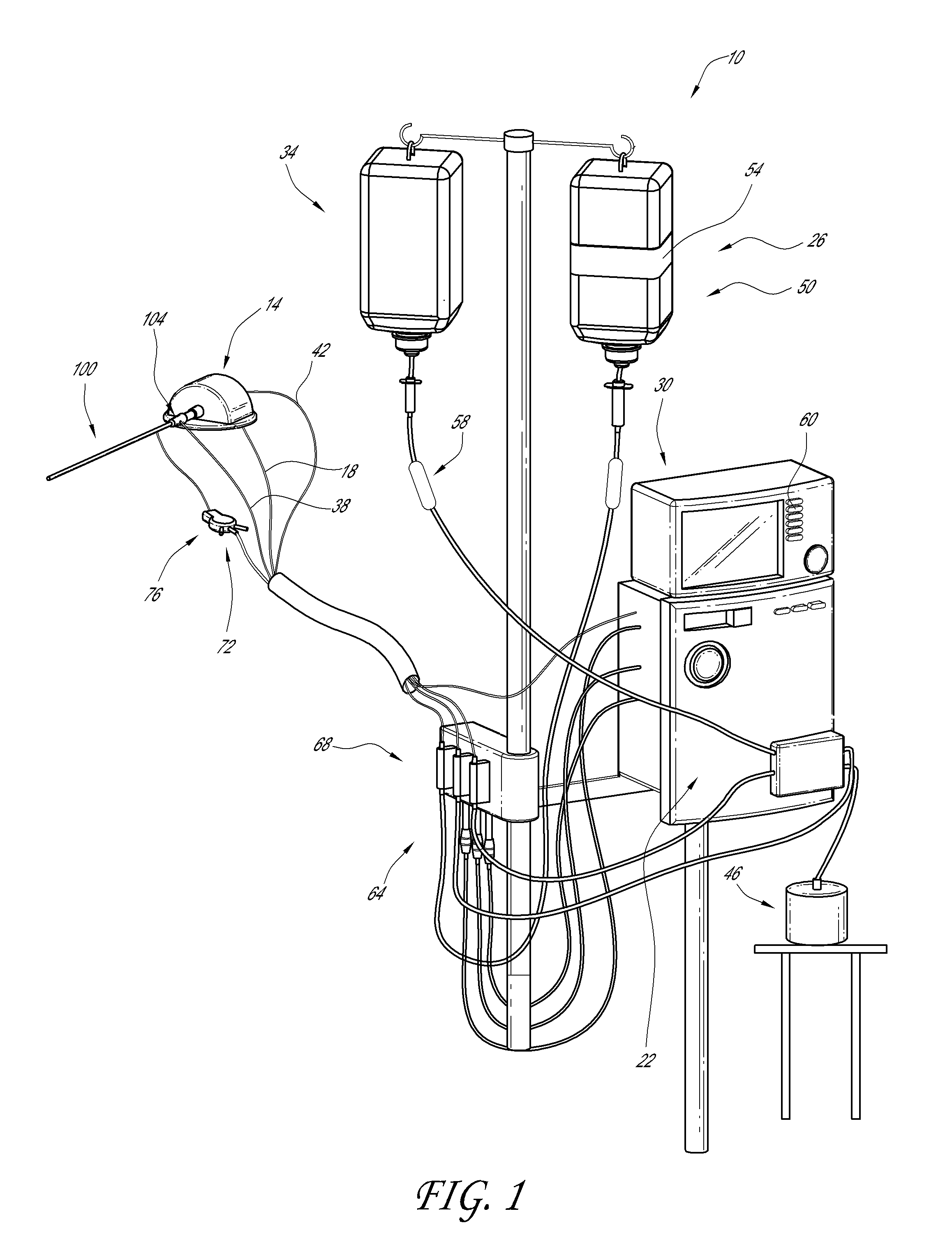
[0065]This application is directed to aspects of heart pumps and components therefor that can be used to treat a patient experiencing cardiac stress, including acute heart failure. Major components of catheter-based pumps that can be applied to a patient percutaneously are described below in Section I. Section II describes distal end features application and performance of heart pumps. In particular, Section II(A) describes structures that facilitate advancement of a heart pump within the vasculature; Section II(B) describes impeller housing configurations that enhance fluid handling performance; and Section II(C) describes stabilizing structures for an impeller housing to control tip gap clearance. Section III illustrates techniques for reducing the complexity and crossing profile of a catheter assembly. Section IV describes features of an impeller assembly for improved performance when subject to operational loads during a heart pumping procedure. Section V discloses embodiments o...


PUM


Abstract

Disclosed herein are heart pumps that include a catheter assembly and that can be applied percutaneously. Some embodiments include a locking device that prevents components of the catheter assembly from being separated when in use. The catheter assembly can include an expandable tip. In some embodiments, the catheter assembly includes a housing having a wall structure, a portion of which can have a bulbuous shape or can be deformable. In other embodiments, the housing can be configured to reduce fluttering or deflection of the housing and / or to maintain a gap between the housing and an impeller blade disposed therein.

Description

CROSS-REFERENCE TO RELATED APPLICATIONS[0001]This application claims priority to U.S. Provisional Application Ser. No. 61 / 430,146 filed Jan. 5, 2011 entitled Impeller Housing For Percutaneous Heart Pump, which is hereby incorporated by reference herein for all purposes.BACKGROUND OF THE INVENTION[0002]1. Field of the Invention[0003]This application is directed to heart pumps that can be applied percutaneously.[0004]2. Description of the Related Art[0005]Heart disease is a major health problem that claims many lives per year. After a heart attack, only a small number of patients can be treated with medicines or other non-invasive treatment. However, a significant number of patients can recover from a heart attack or cardiogenic shock if provided with mechanical circulatory support.[0006]In a conventional approach, a blood pump having a fixed cross-section is surgically inserted a heart chamber, such as into the left ventricle of the heart and the aortic arch to assist the pumping fun...

Claims


Application Information

Patent Timeline
Patent Type & Authority Patents(United States)
IPC IPC(8): A61N1/362
CPCA61M25/04A61M2025/0024A61M2025/0096A61M60/414A61M60/148A61M60/411A61M60/81A61M60/216A61M60/13A61M60/806
Inventor CAMPBELL, ROBERT L.FITZGERALD, KEIFHARRISON, WILLIAM JAMESLESCHINSKY, BORISMALLISON, THOMAS M.MCBRIDE, MARK W.ROSLUND, ADAMWALTERS, DANIEL A.YUEN, PHYLLIS
Owner PENN STATE RES FOUND
Learn More