
Imaging detector and method of manufacturing

a detector and manufacturing method technology, applied in the direction of instruments, radiation controlled devices, optical radiation measurement, etc., can solve the problems of reducing resolution, reducing sensitivity, and reducing resolution, so as to achieve the effect of reducing sensitivity and reducing resolution

Inactive Publication Date: 2013-07-16
GENERAL ELECTRIC CO
View PDF9 Cites 11 Cited by
  • Summary
  • Abstract
  • Description
  • Claims
  • Application Information

AI Technical Summary

Benefits of technology

The patent describes a nuclear medicine imaging detector with two layers of detection separated by an opening, as well as a collimator. The detector layers are mounted close to the collimator, with the second layer having an opening through which to detect gamma rays. This design allows for improved image quality and faster detection times. The detector can be manufactured by aligning and mounting multiple detector layers within a single module with a pinhole collimator. Overall, the invention provides a more efficient and effective means for detecting nuclear medicine in images.

Problems solved by technology

However, when designing collimators a tradeoff exists between resolution and sensitivity.
In contrast, a high sensitivity collimator accepts radiation from a wider range of angles, which increases the sensitivity, but reduces resolution.
However, such designs may perform unsatisfactorily in different applications.
Accordingly, known collimator designs often require one or more compromises.
Thus, these designs may result in detectors that have less than optimal imaging for a particular application.

Method used


Image

  • Imaging detector and method of manufacturing
  • Imaging detector and method of manufacturing
  • Imaging detector and method of manufacturing

Examples


Embodiment Construction

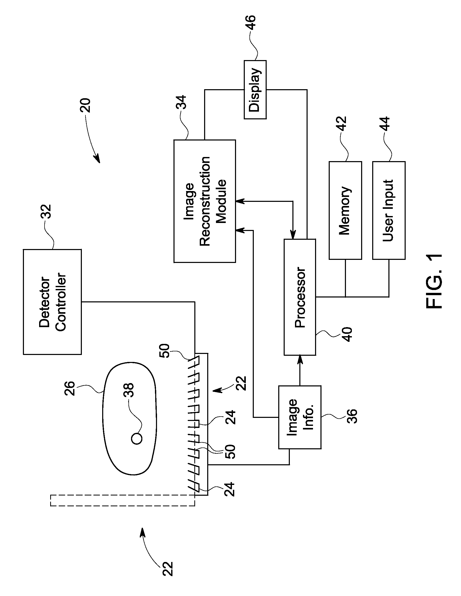
[0029]The following detailed description of certain embodiments, will be better understood when read in conjunction with the appended drawings. To the extent that the figures illustrate diagrams of the functional blocks of various embodiments, the functional blocks are not necessarily indicative of the division between hardware circuitry. Thus, for example, one or more of the functional blocks (e.g., processors, controllers or memories) may be implemented in a single piece of hardware (e.g., a general purpose signal processor or random access memory, hard disk, or the like) or multiple pieces of hardware. Similarly, the programs may be stand alone programs, may be incorporated as subroutines in an operating system, may be functions in an installed software package, and the like. It should be understood that the various embodiments are not limited to the arrangements and instrumentality shown in the drawings.

[0030]As used herein, an element or step recited in the singular and proceed...


PUM


Abstract

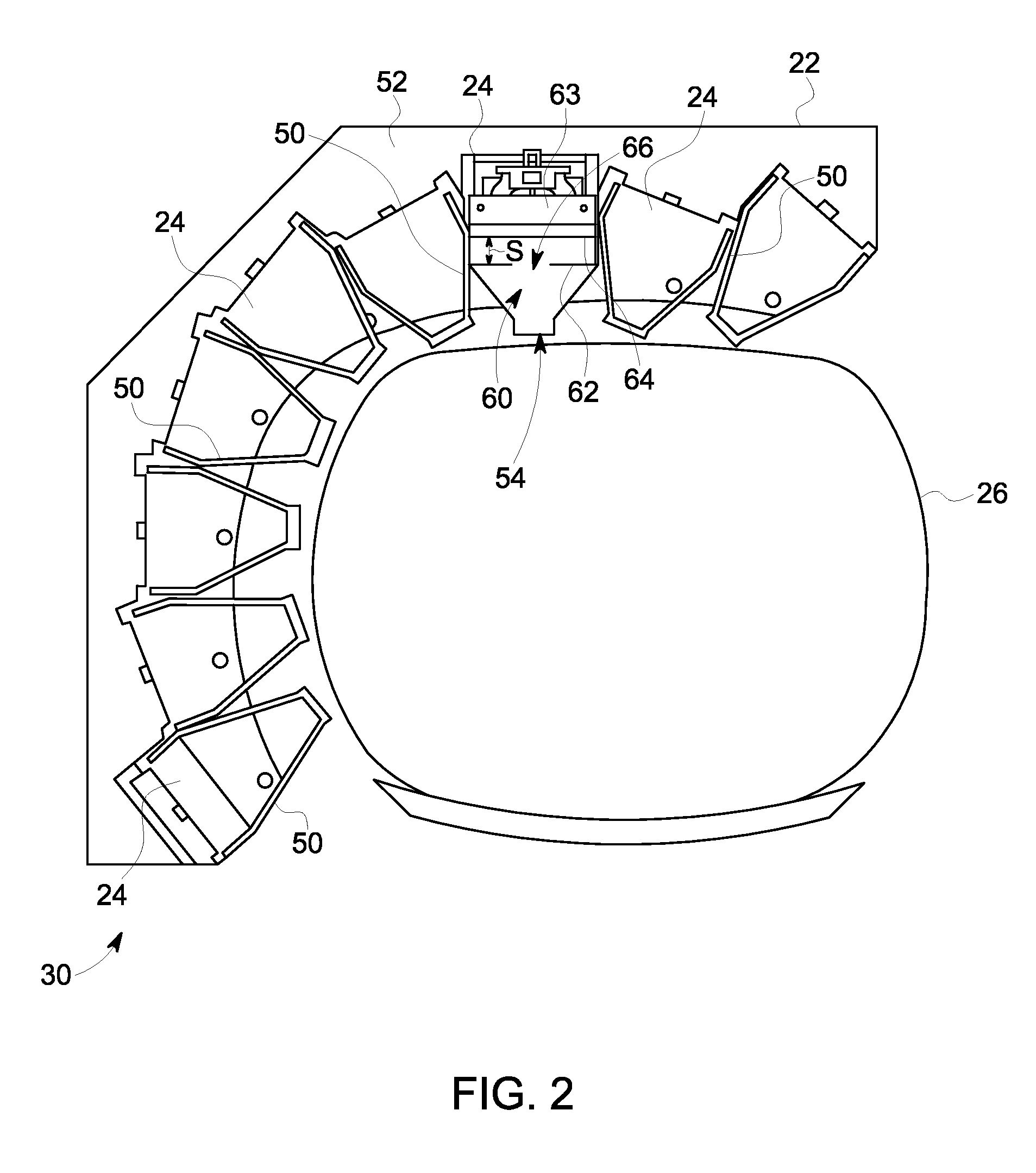
Imaging detectors and methods of manufacturing are provided. One imaging detector includes a first detector layer within a detector module and a second detector layer within the detector module and spaced apart from the first detector layer, wherein the second detector layer has an opening therethrough. The imaging detector also includes a collimator mounted to the detector module, wherein the collimator is one of a single pinhole collimator or a multi-pinhole collimator. Additionally, the second detector layer is mounted within the detector module closer to an opening of the collimator than the first detector layer.

Description

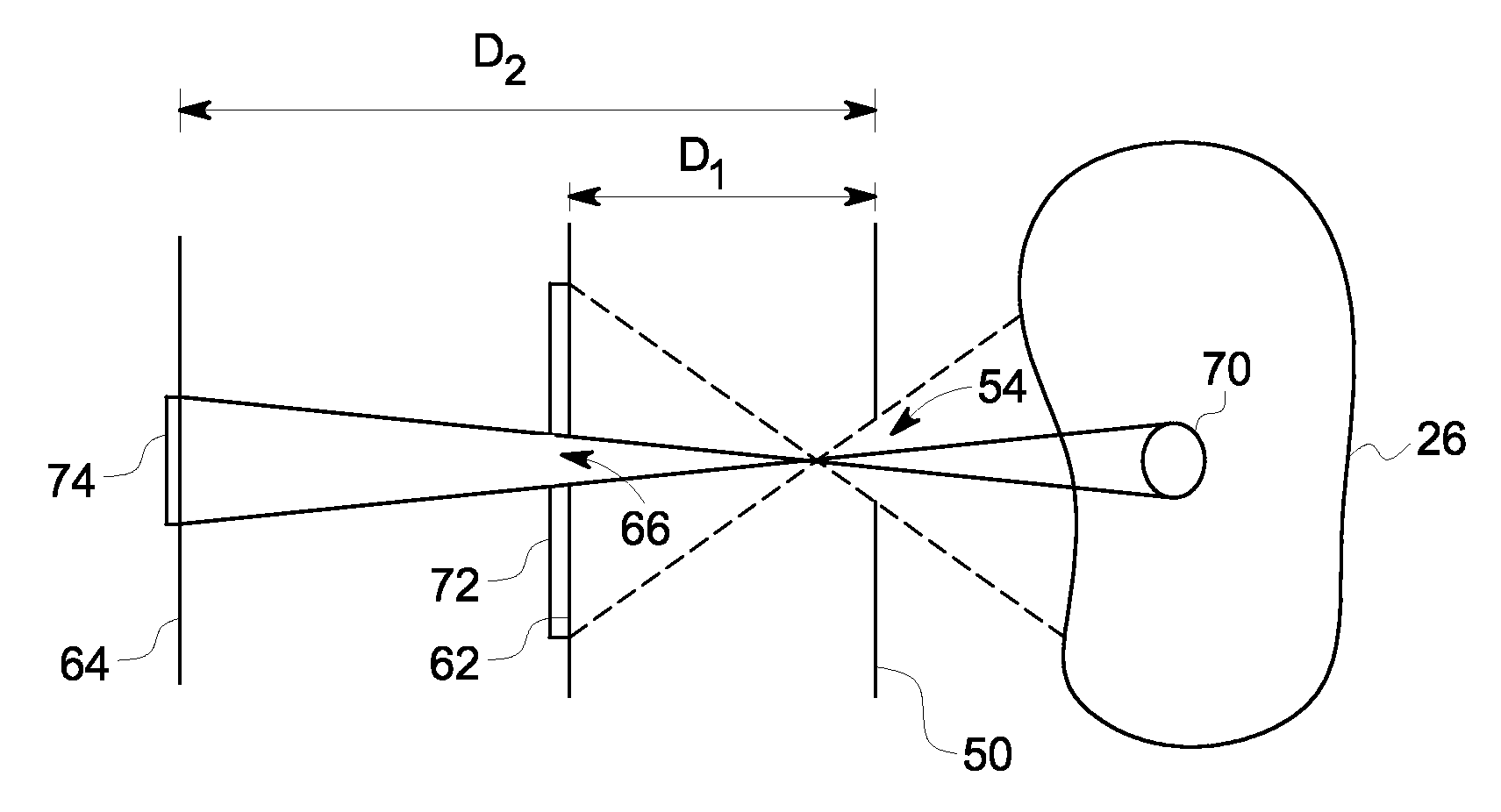
BACKGROUND[0001]In NM imaging, radiopharmaceuticals are injected into a person and then detectors (e.g., gamma cameras), typically mounted on a gantry, capture and form images from the radiation emitted by the radiopharmaceuticals. The NM images primarily show physiological function of, for example, a patient or a portion of a patient being imaged.[0002]Collimation may be used to create an image of radiation-emitting objects in the field of view of the detectors. Different types of collimation are known, for example, different shapes and configurations of collimators are known for use in different types of applications. However, when designing collimators a tradeoff exists between resolution and sensitivity. For example, a high-resolution collimator views a very narrow column of activity from the patient, and therefore provides high spatial resolution, but at a reduced sensitivity. In contrast, a high sensitivity collimator accepts radiation from a wider range of angles, which incre...

Claims


Application Information

Patent Timeline
Patent Type & Authority Patents(United States)
IPC IPC(8): H01L27/146
CPCH01L31/085A61B6/42A61B6/037A61B6/06
Inventor HEUKENSFELDT JANSEN, FLORIBERTUS P. M.HEFETZ, YARON
Owner GENERAL ELECTRIC CO
Learn More