Hybrid analog-to-digital converter, an image sensor and a method for providing a plurality of digital signals

a digital converter and hybrid technology, applied in analogue-digital converters, transmission systems, instruments, etc., can solve the problems of severe design demands for adc, large area and power requirements of adc, and large area requirements for adc, so as to reduce the area required for slope conversion in the converting circuit, improve the conversion rate to power and area ratio, and improve the effect of conversion speed

Inactive Publication Date: 2013-07-23
FRAUNHOFER GESELLSCHAFT ZUR FOERDERUNG DER ANGEWANDTEN FORSCHUNG EV
View PDF22 Cites 13 Cited by
  • Summary
  • Abstract
  • Description
  • Claims
  • Application Information

AI Technical Summary

Benefits of technology

[0018]It is a key idea of embodiments of the present invention that a better conversion rate to power and area ratio within an analog-to-digital converter can be achieved, if the analog-to-digital converter comprises a plurality of converting circuits, each configured to combine a successive approximation conversion with a slope conversion and if a variable reference voltage (for example, a global ramp or global slope) is provided by a common variable reference voltage provider to all of the converting circuits. By using a common variable reference voltage provider for all converting circuits, the area necessitated for the slope conversion in the converting circuit can be reduced, compared to concepts in which every converting circuit generates its own variable reference voltage for performing the slope conversion, for example, in the case of the described concept in the introductory part of this application, using the dual slope integrator.
[0019]It is an advantage of embodiments of the present invention that by combining advantages of successive approximation conversion (high conversion speed) and slope conversion (small area necessitated), and by using a common variable reference voltage provider to provide the common variable reference voltage used during slope conversion, a better conversion rate to power and area ratio can be achieved.

Problems solved by technology

In image sensors the power and area requirements for analog to digital converters set significant limitations for resolution and frame rate.
The pixel race is still ongoing, which leads to severe design demands for the ADC.
In megapixel image sensors several thousand columns (e.g. 4000 and more) with a spacing of 1.5 μm to 10 μm result in tough constrains for the area and power of the ADC.
Due to the number of columns, the available power per converter is limited.
As a result, a warming of the image sensor, which leads to an increase in the dark current of the photodiodes (or in general of the photo detectors) of the image sensor, which is not tolerated.
Otherwise may the increase in dark current lead to a decrease in image quality.
As it can be seen, a problem with image sensors is the parallel digitization of a high number of channels with a very limited area and power.
The main drawback of this architecture is the limited space and power.
Although column pitch can be usually doubled by dividing the ADC to top and bottom of the imager (as it is shown in FIG. 8), however, it is still very small for integrating an analog-to-digital converter for each column.
Not many analog-to-digital converter architectures are easily integratable in this space.
A popular approach is a single slope implementation, but this architecture is not feasible for increasing pixel counts and ADC resolution as the time for the comparator is reduced by both (by the increasing pixel counts and the increasing ADC resolution).
In conventional image sensors, these slope converters are used very frequently, but, as mentioned, this approach is not applicable for larger image sensors (comprising several megapixels) and with higher resolutions (equal to or above 12 bits), because of the necessitated time for the comparator decisions becoming too low.

Method used


Image

  • Hybrid analog-to-digital converter, an image sensor and a method for providing a plurality of digital signals
  • Hybrid analog-to-digital converter, an image sensor and a method for providing a plurality of digital signals
  • Hybrid analog-to-digital converter, an image sensor and a method for providing a plurality of digital signals

Examples


Embodiment Construction

[0034]Before embodiments of the present invention are explained in greater detail in the following taking reference to the figures, it is to be pointed out that the same or functionally equal elements are provided with the same reference numbers, and that a repeated description of these elements will be omitted. Hence, the description of the elements provided with the same reference numbers is mutually interchangeable and / or applicable in the various embodiments.

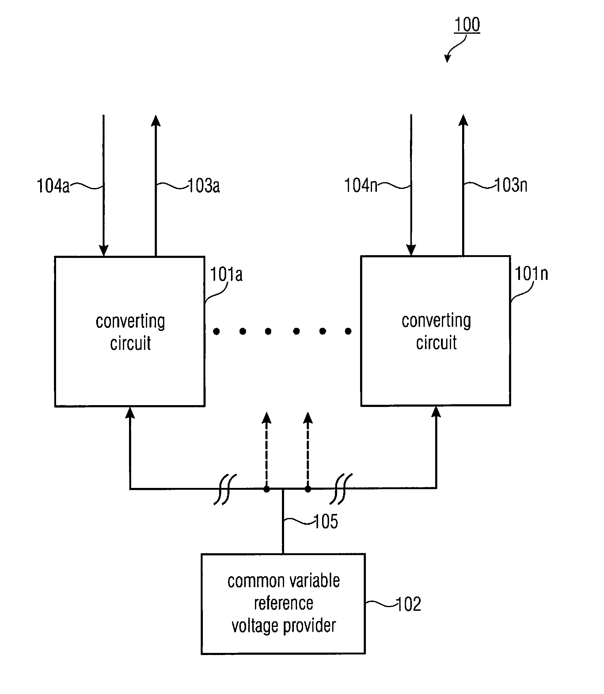
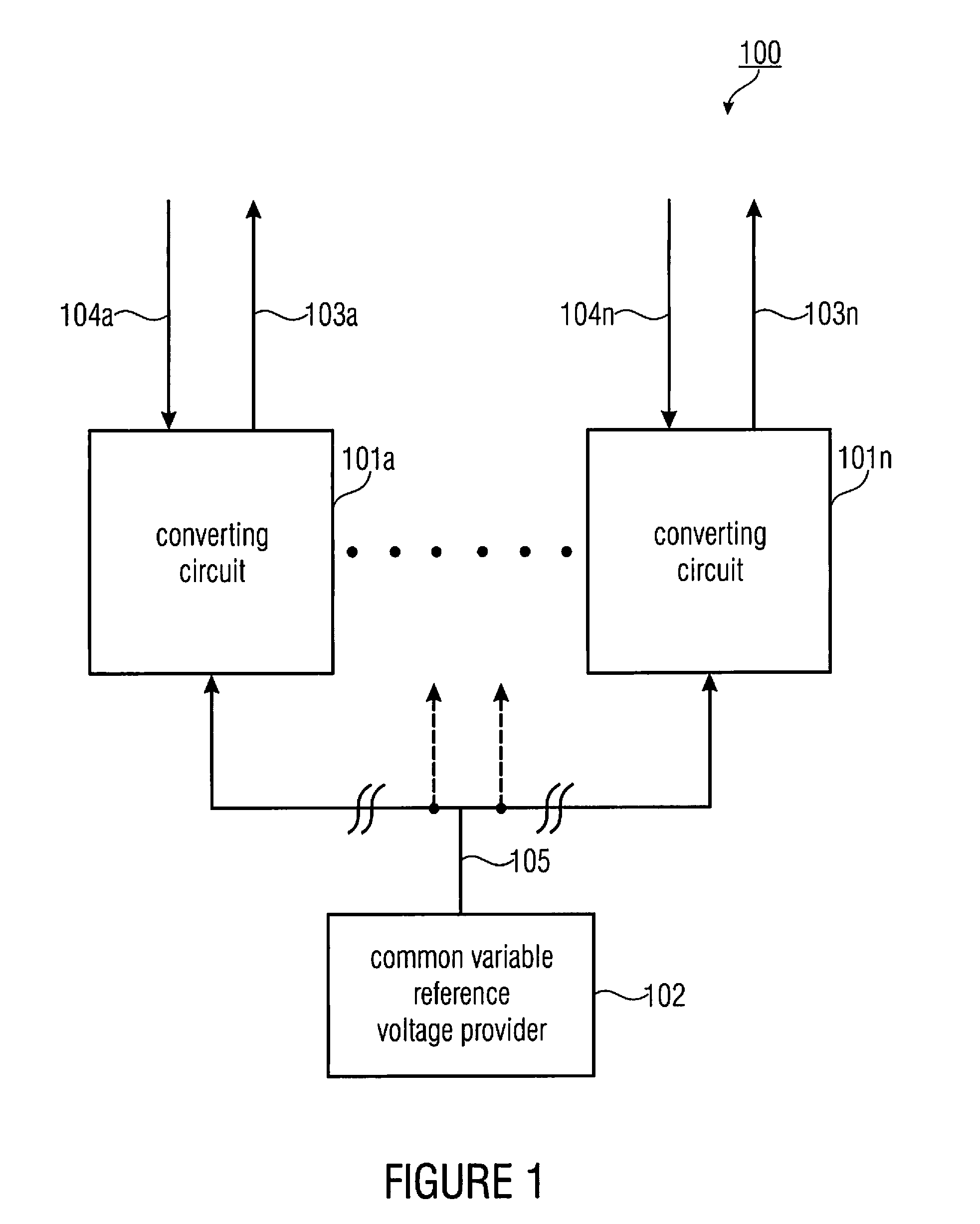
[0035]FIG. 1 shows a block diagram of a hybrid analog-to-digital converter 100. The hybrid analog-to-digital converter 100 comprises a plurality of converting circuits 101a to 101n and a common variable reference voltage provider 102. Each of the converting circuits 101a to 101n is configured to provide a digital signal 103a to 103n based on an analog input signal 104a to 104n by performing a successive approximation conversion to obtain, as a result of the successive approximation conversion, a first number of bits of the d...


PUM


Abstract

A hybrid analog-to-digital converter includes a plurality of converting circuits. Each converting circuit is configured to provide a digital signal based on an analog input signal by performing a successive approximation conversion to obtain, as a result of the successive approximation conversion, a first number of bits of the digital signal, and by subsequently performing a slope conversion based on a common variable reference voltage to obtain a second number of bits of the digital signal, the second number of bits corresponding to a residual between the analog input signal and the result of the successive approximation conversion. The hybrid analog-to-digital converter further includes a common variable reference voltage provider configured to provide to each converting circuit of the plurality of converting circuits the common variable reference voltage.

Description

CROSS-REFERENCE TO RELATED APPLICATIONS[0001]This application claims priority from European Patent Application No. 10171610.8, which was filed on Aug. 2, 2010, and is incorporated herein in its entirety by reference.BACKGROUND OF THE INVENTION[0002]Embodiments of the present invention provide a hybrid analog-to-digital converter, which may be employed in image sensors for digital still cameras or digital video cameras. Further embodiments of the present invention provide an image sensor, which may be employed in digital still cameras or digital video cameras. Further embodiments of the present invention provide a method for providing a plurality of digital signals based on a plurality of analog input signals.[0003]Different approaches exist for the conversion of a plurality of analog-to-digital channels (for example, several thousands). Due to the high number of converters necessitated, the parameters power and area have significant borders, limiting a maximum number of converters, ...

Claims


Application Information

Patent Timeline
Patent Type & Authority Patents(United States)
IPC IPC(8): H03M1/38H03M1/12H01L27/146
CPCH03M1/145H03M1/123H03M1/466H03M1/56H03M1/804
Inventor NEUBAUER, HARALDHAUER, JOHANN
Owner FRAUNHOFER GESELLSCHAFT ZUR FOERDERUNG DER ANGEWANDTEN FORSCHUNG EV
Why Eureka
Try Eureka