Adaptive depth of field sampling

a depth sampling and depth of field technology, applied in the field of computer graphics, can solve the problems of increasing the amount of time and computing resources needed to render the image, and aliasing effects

Active Publication Date: 2013-07-23
PIXAR ANIMATION
View PDF4 Cites 57 Cited by
  • Summary
  • Abstract
  • Description
  • Claims
  • Application Information

AI Technical Summary

Benefits of technology

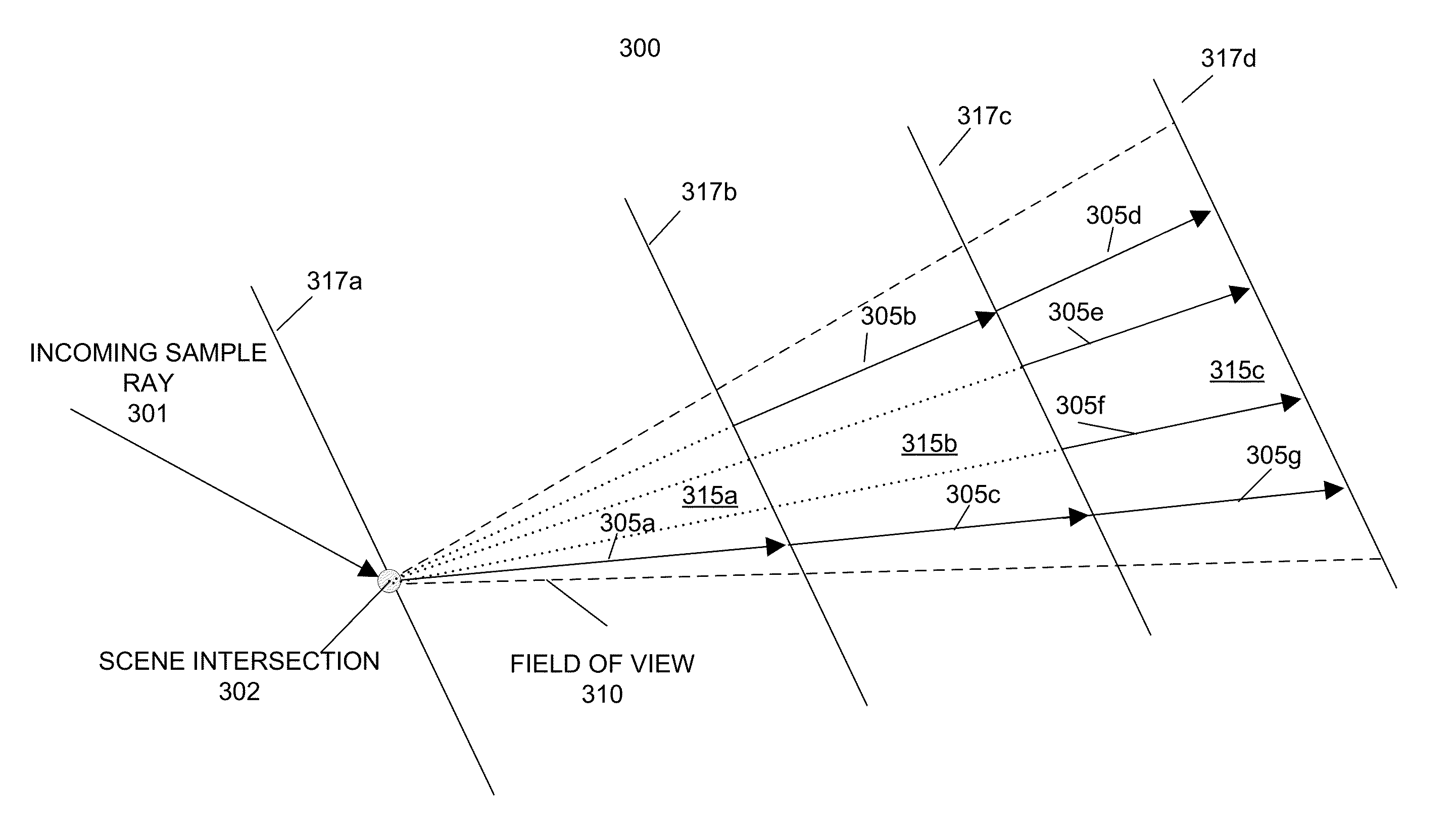
[0010]In an embodiment, the number of sample rays in each depth region may increase monotonically with distance along a line of sight from an image sample point for effects such as reflection, refraction, and illumination. In another embodiment, the number of sample rays in each depth region may increase monotonically with distance from a focal plane for effects such as depth of field.

Problems solved by technology

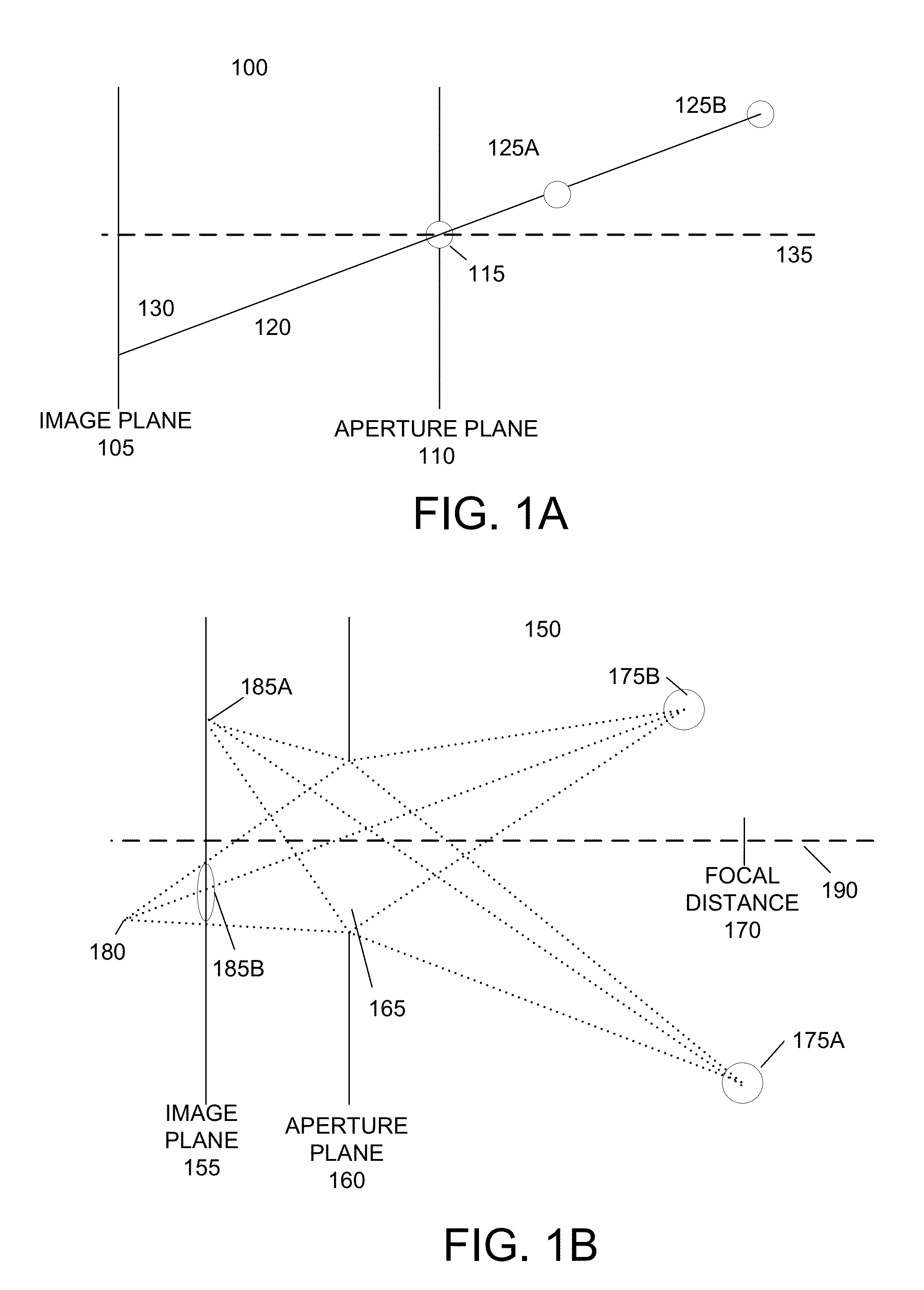
One problem with these sampling-based approaches for generating effects such as illumination, shadowing, reflection, refraction, and depth of field is aliasing of distant objects.
This results in aliasing effects.
However, increasing the number of image sample points greatly increases the amount of time and computing resources needed to render the image.
Moreover, many of the additional points will sample objects close to the sampling ray origin, and thus are redundant.

Method used


Image

  • Adaptive depth of field sampling
  • Adaptive depth of field sampling
  • Adaptive depth of field sampling

Examples


first embodiment

[0079]In a first embodiment, sample rays previously removed depth regions in front of the focal plane 577, such as sample rays 590a, 590b, and 590c, are restored to depth regions behind the focal plane 577. For example, depth region 585e includes an additional sample ray in the form of sample ray 590b′, which is a continuation of previously removed sample ray 590b. In this example, sample ray 590b may sample the scene 570 in depth regions 585a and 585b and sample ray 590b′ may sample the scene in depth regions 585e, 585f, 585g, and potentially any further depth regions.

second embodiment

[0080]In a second embodiment, new sample rays unrelated to the sample rays previously removed may be added to depth regions behind the focal plane 577. For example, depth region 585g includes sample rays 590d and 590b′ carried over from depth region 585f. Depth region 585g also includes additional sample ray 590e. Sample ray 590e is a new sample ray that has no counterpart in any of the previous depth regions 585.

[0081]As in the example of FIG. 5A, an embodiment of the invention may use back-tracing of sample rays to prevent occlusion errors. An embodiment of the invention back-traces any sample ray intersecting an object or other scene element to determine if this sample ray would have also intersected any objects or scene elements in previous depth regions where the sample ray was not used. If the sample ray does intersect an object or scene element in a previous depth region, then this sample ray's contribution to the image sample or subsample is set to zero.

[0082]For example, sa...


PUM


Abstract

Adaptive sampling alleviates aliasing by partitioning the field of view of an image sample point into depth regions. Portions of the scene are sampled within a depth region using sample rays. If a sample ray is not completely occluded in the depth region, corresponding sample rays are evaluated in adjacent depth regions. Sample rays can be recursively evaluated in further depth regions until all the subsamples intersect opaque objects or a depth limit or transparency threshold is reached. The value of an image sample point is the weighted combination of sample rays. The number of sample rays in each depth region may increase monotonically with distance along a line of sight from an image sample point for effects such as reflection, refraction, and illumination. The number of sample rays in each depth region may increase monotonically with distance from a focal plane for effects such as depth of field.

Description

BACKGROUND OF THE INVENTION[0001]The present invention relates to the field of computer graphics, and in particular to systems and methods for optimizing depth of field effects in computer graphics images. Many computer graphic images are created by mathematically modeling the interaction of light with a three dimensional scene from a given viewpoint. This process, called rendering, generates a two-dimensional image of the scene from the given viewpoint, and is analogous to taking a photograph of a real-world scene. Animated sequences can be created by rendering a sequence of images of a scene as the scene is gradually changed over time. A great deal of effort has been devoted to making realistic looking and artistically compelling rendered images and animations.[0002]Many rendering effects are performed by sampling a three-dimensional scene at discrete points. The renderer determines one or more attribute values, such as color, transparency, or depth, for the sample of the three-di...

Claims


Application Information

Patent Timeline
Patent Type & Authority Patents(United States)
IPC IPC(8): G06T15/00
CPCG06T15/06G06T15/503G06T2200/12
Inventor COOK, ROBERT L.CARPENTER, LOREN
Owner PIXAR ANIMATION
Why Eureka
Try Eureka