
Lithographic error reduction by pattern matching

a pattern matching and lithographic error technology, applied in the field of lithographic error reduction, can solve the problems of error base, difficulty in challenging the complexity of waiver pattern, and the difficulty of describing waiver pattern using a standard verification language,

Inactive Publication Date: 2013-07-23
GLOBALFOUNDRIES INC
View PDF15 Cites 1 Cited by
  • Summary
  • Abstract
  • Description
  • Claims
  • Application Information

AI Technical Summary

Benefits of technology

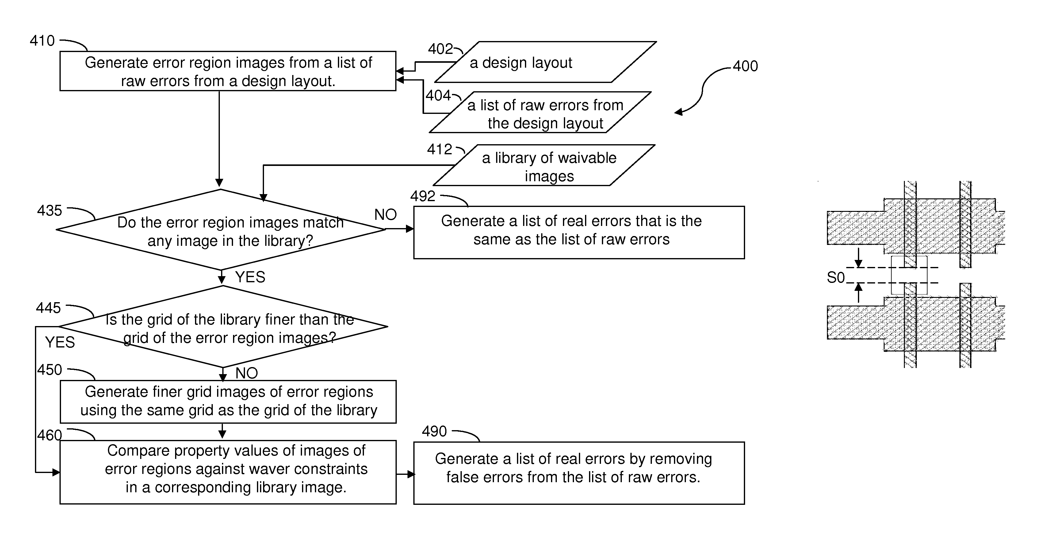
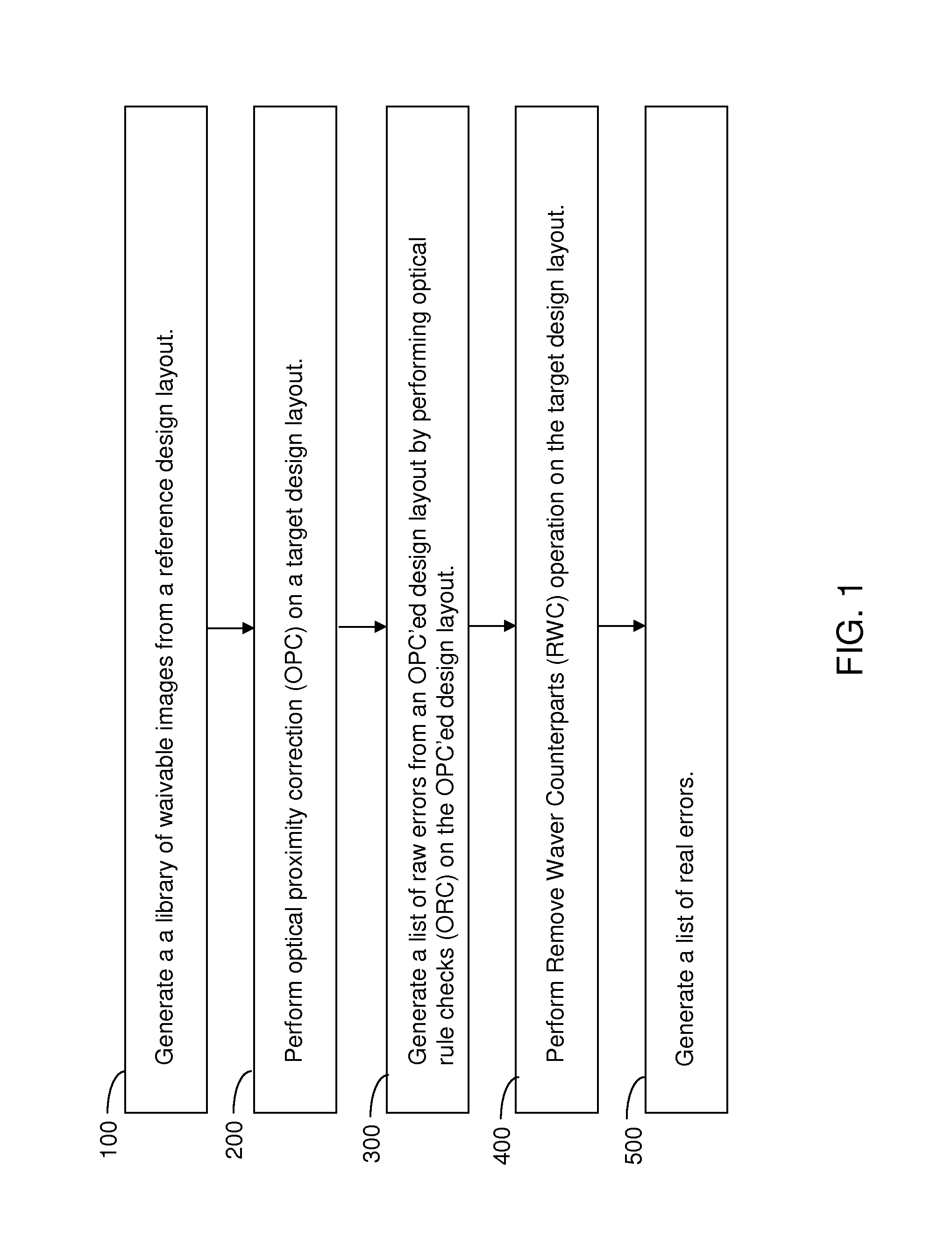
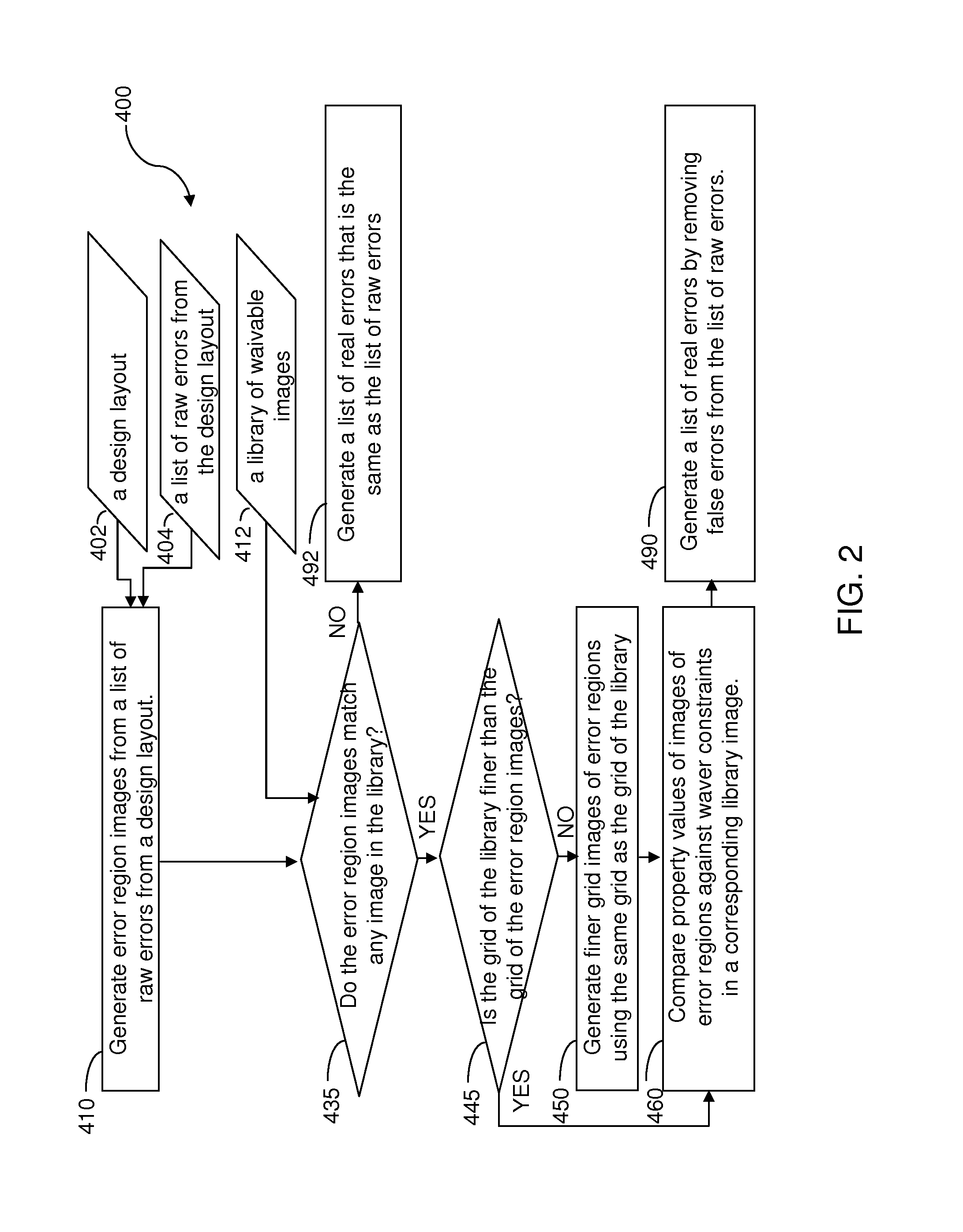
The patent describes a method and system for generating a list of real errors from a list of raw errors. This is useful in identifying and correcting errors in a design layout. The method involves creating a library of waivable images with corresponding waiver constraints, running an optical rule checks program on a target design layout to identify raw errors, generating error region images that match with the raw errors, and removing a subset of the raw errors to generate a list of real errors. The system includes a data storage unit and a computing means for performing the method. The technical effect of this patent is to provide a more efficient and accurate way to identify and correct errors in design layouts.

Problems solved by technology

The error base includes errors that ultimately require pattern corrections thereupon and errors that are associated portions of the pattern that can be lithographically printed safely, i.e., without causing yield or reliability issues, despite being identified as errors.
A persistent challenge in the verification of any design layout is to identify the waivers among the error database so that efforts to correct the design layout can be concentrated only on real errors.
The difficulty of the challenge arises from the complexity of waiver patterns, i.e., the patterns for the waivers.
Thus, describing the waivers employing a standard verification language becomes very tedious, and is prone to generating unexpected results.
The waiver patterns have a dynamic nature, hence, updating all production verification recipes to waive non-critical patterns can consume many hours of intensive manual examination.

Method used


Image

  • Lithographic error reduction by pattern matching
  • Lithographic error reduction by pattern matching
  • Lithographic error reduction by pattern matching

Examples


example

[0060]In a comparative example, an existing ORC run was used to test the efficiency of a prior art method of modifying design layouts that does not employ any pattern matching after generation of raw errors in a design layout. The ORC run had 1138 ORC errors inside SRAM cells. The ORC errors were present across patterns as well as on similar patterns. Usually, if there are similar patterns the property value remains same but in this case the property value depended on the location of these similar patterns. If the pattern was present on an edge of SRAM array, then it was having less strict waiver value than the one which was present in the active region of an array. When these errors were reviewed according to the existing review process, it was found that some of the errors have waivers and some were real errors. It took around about 6 hours to manually review them and this procedure has to be repeated for future ORC reviews of designs containing similar SRAM cells.

[0061]In a first...


PUM


Abstract

A library of waivable images with corresponding waiver constraints is generated. Each of the waivable images is an image of a region of a reference design layout including a raw error as determined by an optical rule checks (ORC) program and does not require a correction for printability on a photoresist layer. A list of raw errors is generated by running the ORC program on a target design layout. Error region images corresponding to the list of raw errors are generated by selecting a region of the target design layout around points corresponding to the raw errors. A list of matches between the library of waivable images and the error region images is generated. By removing a subset of raw errors that correspond to a subset of the list of matches from the list of raw errors, a list of real errors is generated.

Description

BACKGROUND[0001]The present disclosure relates to a method for reducing lithographic errors for manual processing by automatically removing errors that do not require pattern correction, and a system for effecting the same.[0002]A combination of an optical proximity correction (OPC) program and an optical rule checks (ORC) program is employed to analyze a design layout for a semiconductor chip for lithographic errors. Typically, identification of lithographic errors is performed by running a verification recipe with the OPC program and / or the ORC program. The identified lithographic errors are collected in an error database.[0003]The error base includes errors that ultimately require pattern corrections thereupon and errors that are associated portions of the pattern that can be lithographically printed safely, i.e., without causing yield or reliability issues, despite being identified as errors. The errors that require pattern corrections are referred to as real errors. The errors ...

Claims


Application Information

Patent Timeline
IPC IPC(8): G06F17/50
CPCG03F1/44G03F1/36
Inventor CHAUDHARY, ADITYABOUCHARD, PIERRE J.DAVE, KALPESH G.
Owner GLOBALFOUNDRIES INC
Learn More