
Energy saving system and method for cooling computer data center and telecom equipment

a technology for telecom equipment and computer data centers, applied in domestic cooling apparatus, electric apparatus casings/cabinets/drawers, heating types, etc., can solve the problems of poor turnover of large air mass, insufficient ensuring, and considerable difference between discharging cold air near heat sources, so as to prevent thermal failure of electronic equipment and effectively cool the heat sour

Active Publication Date: 2013-07-30
MARTINI VALAN R
View PDF18 Cites 70 Cited by
  • Summary
  • Abstract
  • Description
  • Claims
  • Application Information

AI Technical Summary

Benefits of technology

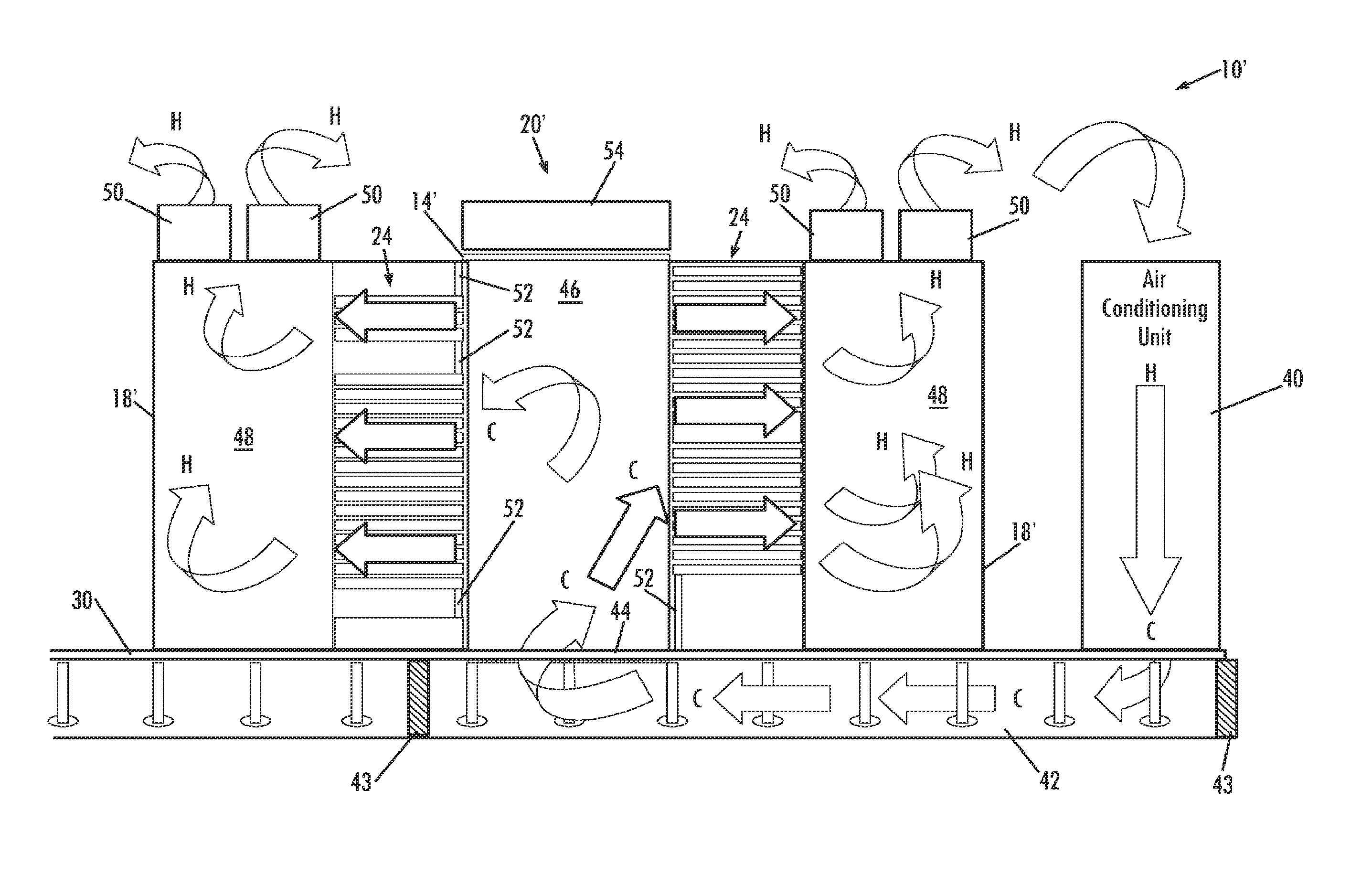
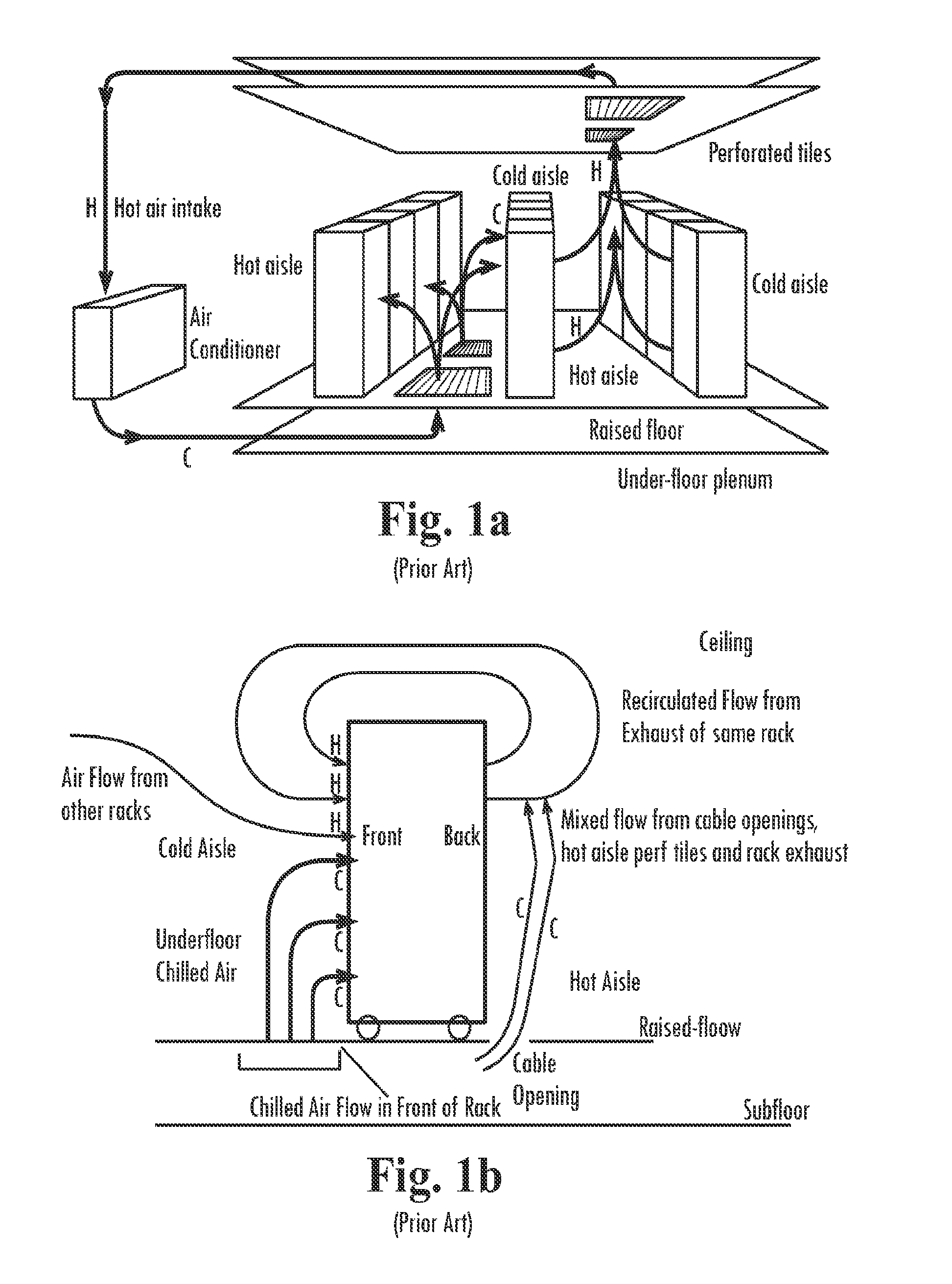
[0016]As a result of these factors, it has been found that most of the cold air generated by all the cooling equipment and chillers is wasted into the general environment, and never actually flows through the heat producing equipment. The cooling air is dispersed as it mixes with warmer air mass within the room at large, and thus the entire air mass obtains temperatures above the cooling air temperature generated by the air handlers. Most electronic equipment racks have low airflow volumes passing through the components within the equipment racks. Flow rates of less than 100-cubic feet of air per minute passing through all of the electronic components in a single equipment rack are common. The tiny fans on the equipment components and circuit boards don't add up to much flow due to the small diameter and other features of the axial fans used to create the airflow. New installation techniques involve installing equipment in very close proximity to other components in the rack, which is an efficient use of space and expensive floor space. However, the close proximity of the equipment further minimizes flow and adds to latent heat soak and heat retained by the heat producing equipment. Thus, these high-density installations are very prone to heat related failure as a result of the buildup of the heat within the rack enclosure. Other than the airflow created by the tiny fans, there may be very little or no airflow around the equipment inside the rack enclosures. Often, exhausted warm air flows to the front side cooling air intake vents of components due to suction created by the air drawn into the components by the tiny fans. This is the worst possible circumstance, wherein equipment is recirculating already warm exhausted air through cooling air intakes. Heat related electronic component failure has become a more common problem, especially at older facilities that may have older air conditioning methods or systems installed. If an older facility installs new electronic equipment, the heat produced can exceed the capacity of the facilities cooling systems. Design and configuration is also a factor in cooling efficiency and can greatly impact the amount of energy consumed to cool telecommunications or data center equipment. How space is utilized is crucial to optimizing cooling performance and maximizing uptime probability and system reliability.
[0057]Lower overall power consumption also means that backup and auxiliary power systems (generators) investments can also be minimized. Battery backup systems must be charged constantly, generators must be operated regularly to provide lubrication to moving parts and to clear fuel and exhaust systems. Generators commonly utilize expensive diesel fuel, gasoline, or natural gas as fuel. Batteries in uninterruptible power supply battery arrays need to be replaced after the useful life is spent. Improper disposal may cause toxic lead to be distributed to water bodies. All batteries release gas during charging. If batteries are nearing the end of their useful life, overcharging can occur and the batteries will overheat, releasing toxic vapors which are hazardous to the facility, electronic equipment, and personnel. Representative embodiments of the present invention can minimize the requirement for these systems, resulting in another potential money and energy savings advantage.

Problems solved by technology

It is now known that merely locating discharge of cooling air from an air handler near heat producing electronic equipment does not necessarily ensure that the cooling air output is actually providing the desired cooling effect toward preventing thermal failure of the electronic equipment.
Indeed, there is a considerable difference between discharging cold air near a heat source, and effectively cooling that heat source in the desired manner.
Most controlled environment rooms soon become stratified, with a layer of excessively damp, much cooler air flowing along the lowest portion of the environment.
Contrary to common thinking, the reality is that a larger controlled environment with relatively low population of electronic equipment require substantially more cooling due to the high volume of the environment causing poor turnover of the large air mass.
Thus, locating high velocity air handlers too close to equipment can have a very negative effect on the cooling efficiency and cooling performance of the entire above floor environment.
In general practice, perforated floor tiles have poor flow output.
As a result of these factors, it has been found that most of the cold air generated by all the cooling equipment and chillers is wasted into the general environment, and never actually flows through the heat producing equipment.
However, the close proximity of the equipment further minimizes flow and adds to latent heat soak and heat retained by the heat producing equipment.
Thus, these high-density installations are very prone to heat related failure as a result of the buildup of the heat within the rack enclosure.
This is the worst possible circumstance, wherein equipment is recirculating already warm exhausted air through cooling air intakes.
Heat related electronic component failure has become a more common problem, especially at older facilities that may have older air conditioning methods or systems installed.
If an older facility installs new electronic equipment, the heat produced can exceed the capacity of the facilities cooling systems.
Design and configuration is also a factor in cooling efficiency and can greatly impact the amount of energy consumed to cool telecommunications or data center equipment.

Method used


Image

  • Energy saving system and method for cooling computer data center and telecom equipment
  • Energy saving system and method for cooling computer data center and telecom equipment
  • Energy saving system and method for cooling computer data center and telecom equipment

Examples


Embodiment Construction

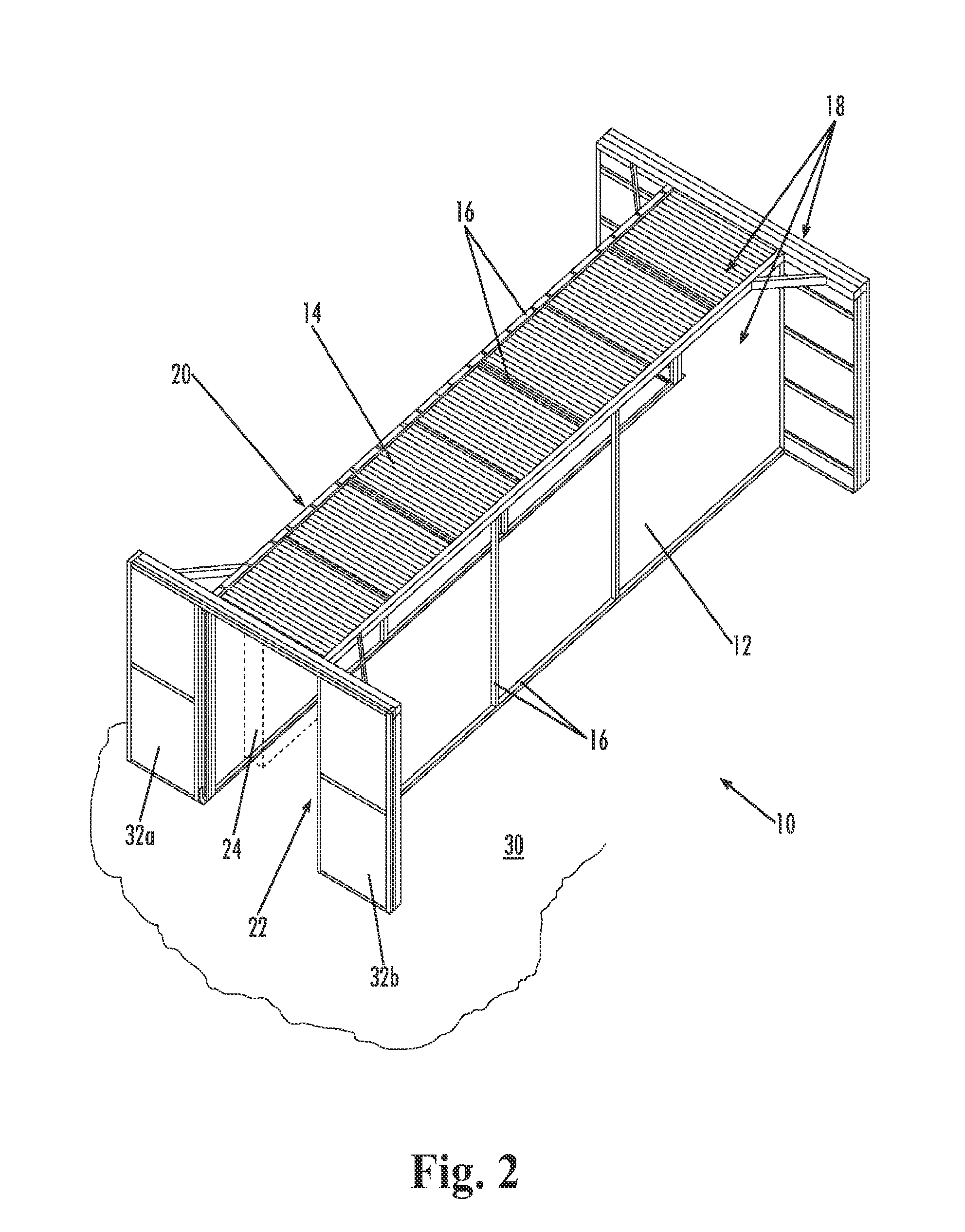
[0068]The present invention may be understood more readily by reference to the following detailed description of the invention taken in connection with the accompanying drawing figures, which form a part of this disclosure. It is to be understood that this invention is not limited to the specific devices, methods, conditions or parameters described and / or shown herein, and that the terminology used herein is for the purpose of describing particular embodiments by way of example only and is not intended to be limiting of the claimed invention. Also, as used in the specification including the appended claims, the singular forms “a,”“an,” and “the” include the plural, and reference to a particular numerical value includes at least that particular value, unless the context clearly dictates otherwise. Ranges may be expressed herein as from “about” or “approximately” one particular value and / or to “about” or “approximately” another particular value. When such a range is expressed, another...


PUM


Abstract

A system and method of reducing consumption of electricity used to cool electronic computer data center, networking, and telecommunications equipment, and to reduce the incidence of thermal failure of electronic components, includes provision of one or more partitions to reduce the volume of the cooled environment supplying coldest possible cooled air from air conditioning systems to a chamber adjacent to the cooling air intake side of electronic components, preventing dilution of the supplied cooling airflow by warmer air from outside of the reduced volume environment, and controlling the delivery of cooling air flow through the reduced volume of the cooled environment.

Description

CROSS-REFERENCE TO RELATED APPLICATION[0001]This application claims priority benefit to U.S. Provisional Patent Application Ser. No. 60 / 804,908, filed Jun. 15, 2006, which application is hereby incorporated herein by reference in its entirety.TECHNICAL FIELD[0002]The present invention relates generally to an energy saving system and method for reducing electricity used to cool computer data center and telecom equipment by reducing the volume of the cooled environment, controlling airflow, and preventing dilution of the cooling air by warmer air from outside of the cooled environment, and thus increasing cooling airflow, to prevent thermal failure of electronic components.BACKGROUND OF THE INVENTION[0003]Effective cooling of data centers and other facilities operating telecommunications or computer equipment is a growing field of endeavor. Electronic components that operate on the flow of electricity create heat in the process of utilizing electrical flow. Modern electronic equipment...

Claims


Application Information

Patent Timeline
Patent Type & Authority Patents(United States)
IPC IPC(8): H05K7/20H05K5/00F25D17/06
CPCF24F11/0001H05K7/20745F24F2011/0075Y02B30/767F24F2221/40F24F11/46
Inventor MARTINI, VALAN R.
Owner MARTINI VALAN R
Learn More