Milling tool for establishing openings in wellbore obstructions

a technology for obstructions and milling tools, applied in the direction of drilling pipes, drilling/well accessories, sealing/packing, etc., can solve the problems of unique and complex design challenges, and achieve the effects of avoiding severe vibration, and reducing the risk of damag

Active Publication Date: 2013-08-06
BAKER HUGHES INC
View PDF28 Cites 7 Cited by
  • Summary
  • Abstract
  • Description
  • Claims
  • Application Information

AI Technical Summary

Benefits of technology

[0006]In preferred embodiments, the milling tool includes a plurality of stabilizing wear pads. Preferably, the wear pads are formed of axially extending strips of copper alloy or similar ate al that are located in a specific spaced circumferential relation around the circumference of the milling tool body and are positioned nearly adjacent to the cutters for cutter protection. The pads disposed upon the shaft portion adjacent the cutting portion present a greater engagement diameter along the shaft portion of the milling tool body than the greatest cutting diameter of the cutters. This permits the milling load to be supported and stabilized when the cutters of the final step are completely through the upper solid portion of the obstruction. during cutting operation, these pads wear away.
[0008]In a further feature of the invention, an annular flow through no-go centralizer preferably surrounds a reduced-diameter shaft portion of the milling tool body. The no-go centralizer is preferably rotationally moveable with respect to the milling tool body. The outside diameter of the centralizer as measured around the centralizer ribs is larger than the milling tool body diameter, such that the centralizer ribs present stop shoulders to engage an upper portion of a wellbore obstruction, thereby stopping cutting progress of the milling tool and signaling to an operator that the desired hole has been established.
[0009]In operation, the milling tool is used to establish openings through wellbore obstructions and create access to hydrocarbon reservoirs into which access was previously restricted by the obstruction. Though general in intended application, the devices and methods of the present invention are particularly well suited to instances wherein the device must bore through wellbore obstructions, such as closed ball valve balls, which include large diameter holes which are transverse to the boring direction. These applications are particularly challenging as both the top and the bottom of the transverse hole are curved. As this curvature is being bored, the cutters of a given step will bear on the obstruction material during a portion of a given revolution of the milling tool and be unsupported during another portion of the revolution. When the bored hole approaches the transverse hole diameter, the arcs in which the cutters are in contact with the obstruction become small. The cutters must be constantly supported to avoid severe vibration, so an alternative means of supporting the cutters must be provided. In accordance with embodiments of the present invention, when cutters are not supported on the top side of the transverse hole, cutters cutting on the bottom side of the hole are in contact with the obstruction. If the cutters of each step substantially perform their cutting in a plane perpendicular to the milling tool axis, it is not always geometrically possible to keep them supported. Thus, the cutters are angled with respect to the milling tool axis so their contact on the top and bottom of the transverse hole is extended over an appreciable boring distance which enables the milling tool to be designed such that it is supported by the cutters in contact with the obstruction for most of the revolution. Even when the cutters at the top and bottom of the transverse hole are fully supported, angling the cutters provides another important benefit of cutting efficiently with a relatively constant applied cutting load by maintaining an approximately constant cut width. As the cutters at the top enter the transverse hole, their cut width becomes progressively narrower as the boring progresses. Conversely, the cutters engaging the bottom of the hole start with a very narrow cut width at contact, and the width grows progressively as the boring progresses. With proper axial spacing, the width of the bottom cut can increase substantially the same amount as the top cut decreases, providing a substantially constant cut width and milling contact area. In addition, once the cutters have passed entirely through the upper solid portion of the obstruction, the milling tool is stabilized by contact between wear pads and the upper solid portion. Hole cutting devices constructed in accordance with the present invention may be used with through-tubing arrangements. These devices apply an essentially constant cutting load, so designs are provided that will operate effectively at a constant load, thereby offering substantial advantages.

Problems solved by technology

The presence of this hole requires the milling tool to bore through curved surfaces at the top and bottom of the hole which presents unique and complex design challenges.

Method used


Image

  • Milling tool for establishing openings in wellbore obstructions
  • Milling tool for establishing openings in wellbore obstructions
  • Milling tool for establishing openings in wellbore obstructions

Examples


Embodiment Construction

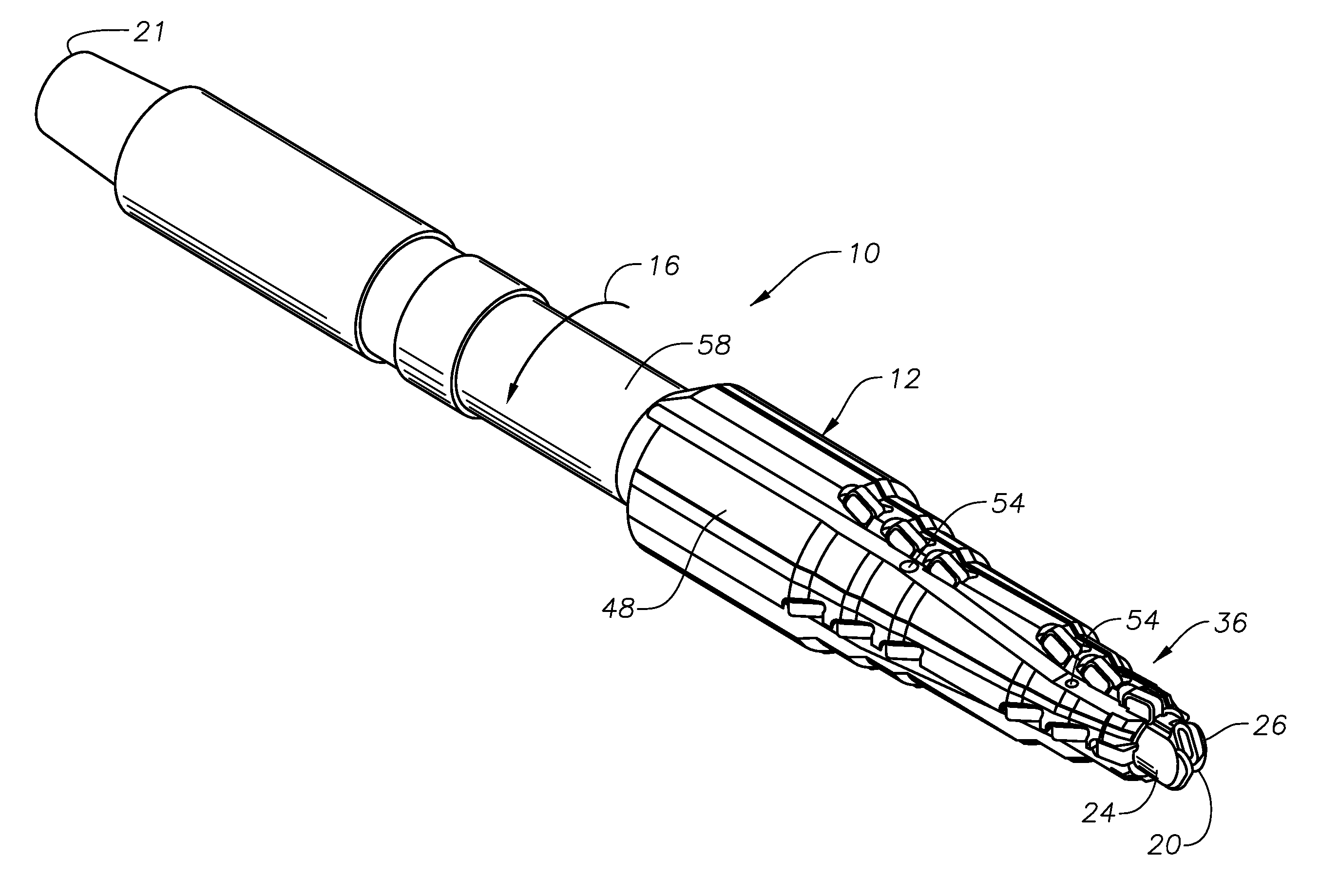
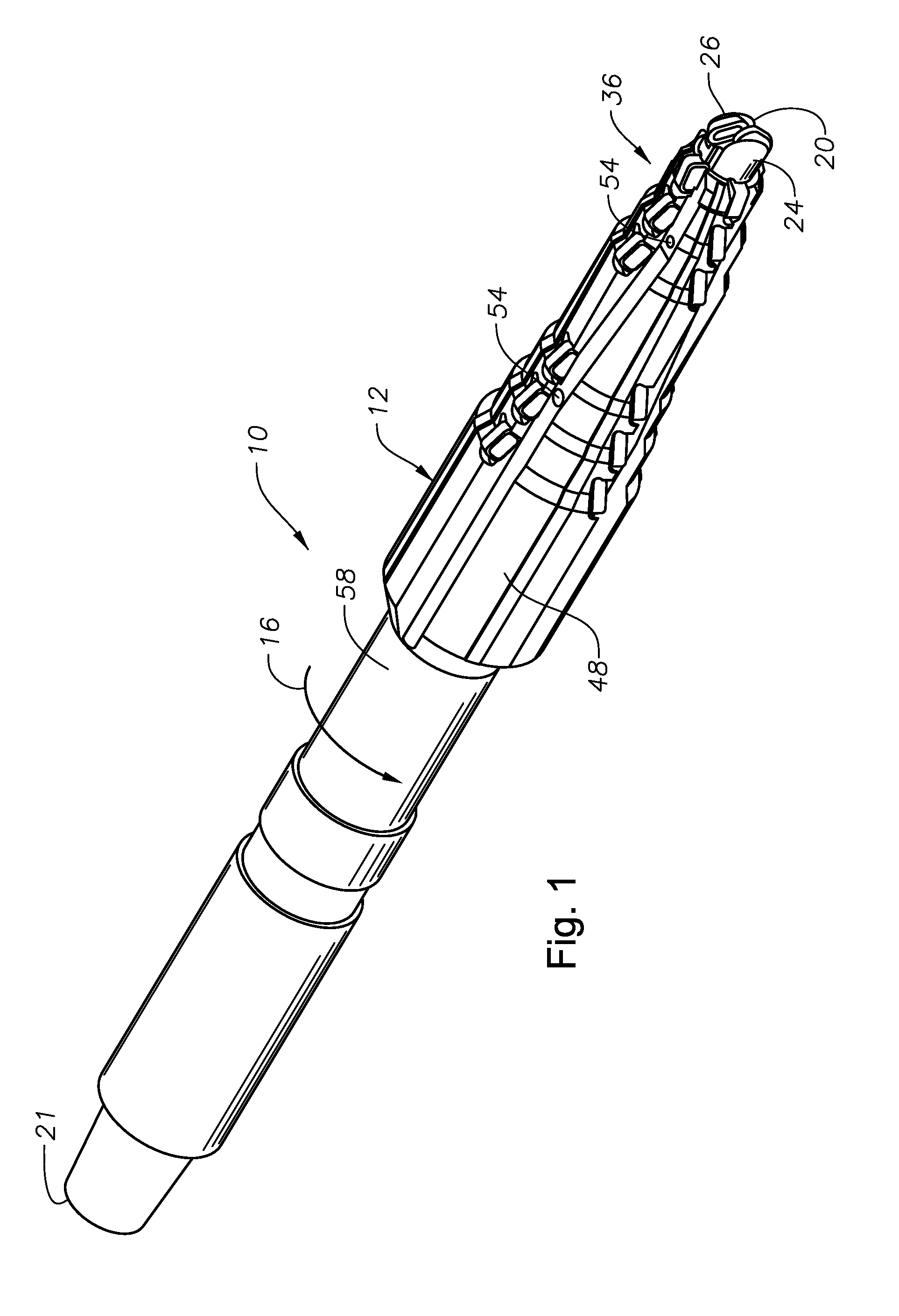
[0031]Referring first to FIGS. 1-8, there is depicted an exemplary milling tool 10 that has been constructed in accordance with the present invention. The milling tool 10 includes a milling tool body 12 that has a shaft / fishing neck. In the event that coiled tubing is used for running the milling tool 10, a mud motor of a type known in the art, is positioned in between the coiled tubing and the milling tool 10 in order to cause the milling tool 10 to rotate as fluid is flowed down through the mud motor. During operation in a wellbore, the milling tool 10 is rotated in the direction indicated by arrow 16.

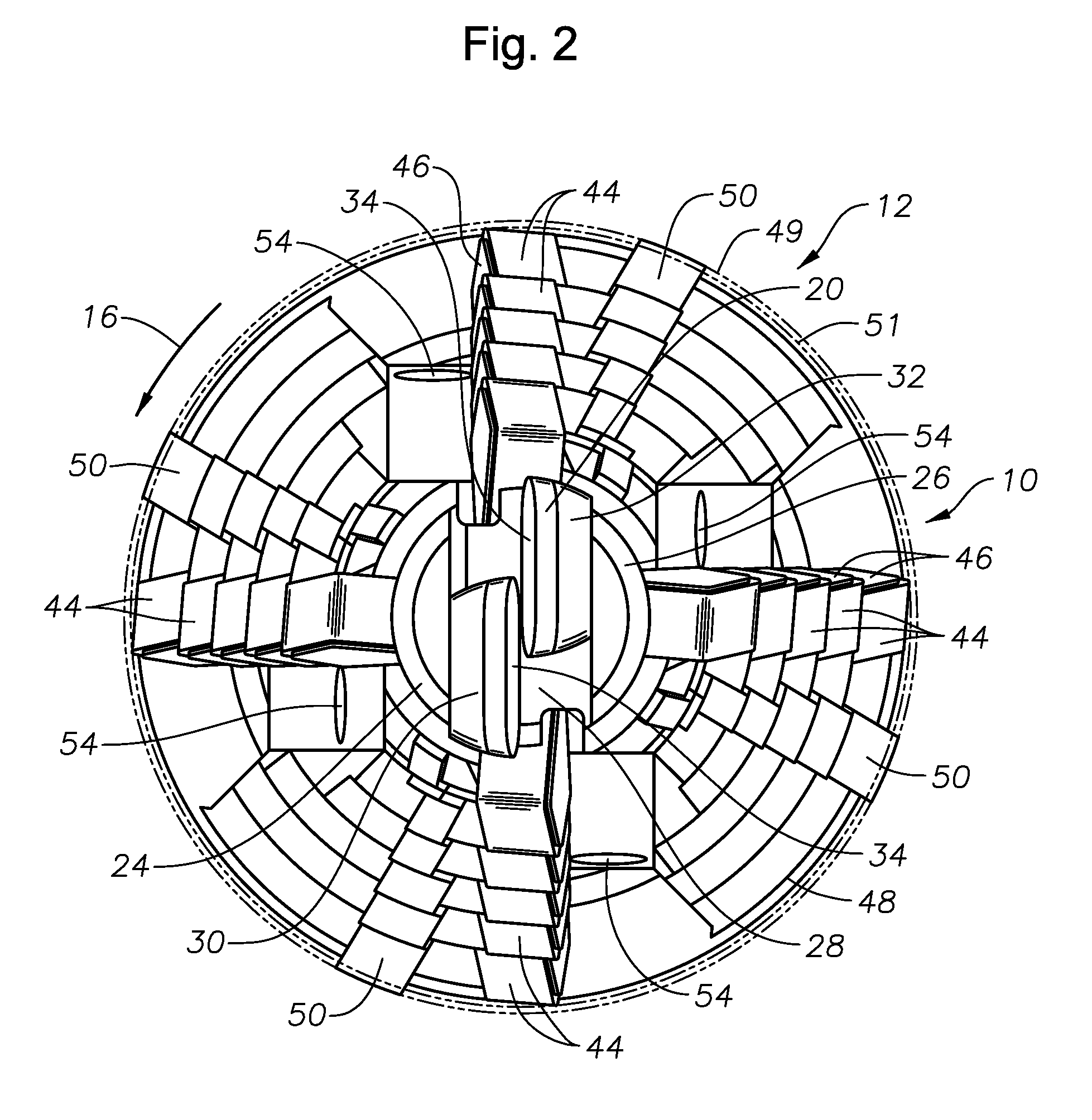
[0032]The milling tool body 12 has a distal end 20 and a proximal end 21. The distal end 20 of the milling tool body 12 presents a nose cutting portion, generally indicated at 22. In a preferred embodiment, the nose cutting portion 22 includes a pair of cutting prongs 24, 26, which protrude axially in the distal direction from cylindrical base 27. Each cutting prong 24, 26 has a gene...


PUM


Abstract

A milling tool which includes a nose cutting portion, a cutting section having a plurality of hardened cutters and a shaft portion. A wear pad is disposed on the cutting section and shaft portion. Upon the shaft portion, the wear pad extends radially outwardly to an engagement diameter that exceeds the maximum cutting diameter of the cutters.

Description

[0001]This application claims priority to U.S. Provisional Patent Application Ser. No. 61 / 247,928 filed Oct. 1, 2009.BACKGROUND OF THE INVENTION1. Field of the Invention[0002]The invention relates generally to systems and methods to form an opening by cutting through an obstruction within a wellbore.2. Description of the Related Art[0003]In the course of wellbore production operations, objects and devices occasionally become undesirably stuck within a production wellbore and are substantially resistant to removal using fishing devices. Such instances might include, for example, when an object, such as a ball valve ball is locked in the closed position such that it cannot be opened using conventional methods. In such instances, the locked closed object is most often generally oriented such that a transverse hole within the object is generally oriented perpendicular to the wellbore.SUMMARY OF THE INVENTION[0004]The present invention provides a milling tool and a method for using such ...

Claims


Application Information

Patent Timeline
Patent Type & Authority Patents(United States)
IPC IPC(8): E21B29/06E21B10/26E21B17/10
CPCE21B29/002E21B29/06
Inventor GUIDRY, CHRISTOPHER W.NAVIN, GURUSWAMIJOPPE, LAMBERTUS C. F.PONDER, ANDREW D.STOWE, CALVIN
Owner BAKER HUGHES INC
Why Eureka
Try Eureka