Quick disconnect coupling

a technology of coupling and quick disconnect, applied in the direction of resilient force resistors, fastening means, gymnastics exercise, etc., can solve the problems of frustrated users of such equipment and eventually stop using such machines

Inactive Publication Date: 2013-08-06
TORQUE FITNESS
View PDF19 Cites 19 Cited by
  • Summary
  • Abstract
  • Description
  • Claims
  • Application Information

AI Technical Summary

Benefits of technology

[0007]A second aspect of the invention is a quick disconnect system including a matable coupling and post. A first embodiment of the system includes the first embodiment of the quick disconnect coupling described above and a post with a flanged head on the distal end of a shaft configured and arranged to (i) engage and separate the pins on the coupling against the bias of the biasing means when inserted into the bore, (ii) allow the biasing means to return the pins to the radial position nearer the longitudinal axis of the bore and thereby prevent withdrawal of the post from the bore after the flanged head is inserted past the pins, and (iii) permit withdrawal of the post from the bore by repositioning the jacket into the second stop position against the bias of the biasing means.
[0008]A second embodiment of the system includes the second embodiment of the quick disconnect coupling described above and a shaft with a mushroom-shaped head on the distal end of the shaft configured and arranged to (i) engage and separate the pins on the coupling against the bias of the biasing means when inserted into the bore, (ii) allow the biasing means to return the pins to the radial position nearer the longitudinal axis of the bore and thereby prevent withdrawal of the post from the bore after the mushroom-shaped head is inserted past the pins, and (iii) permit withdrawal of the post from the bore by repositioning the jacket into the second stop position against the bias of the spring.

Problems solved by technology

While generally effective, experience has shown that users of such equipment tend to become frustrated with and eventually stop using such machines unless the method of interchanging the exercise interface units is quick, easy and intuitive.

Method used


Image

  • Quick disconnect coupling
  • Quick disconnect coupling
  • Quick disconnect coupling

Examples


Embodiment Construction

Nomenclature

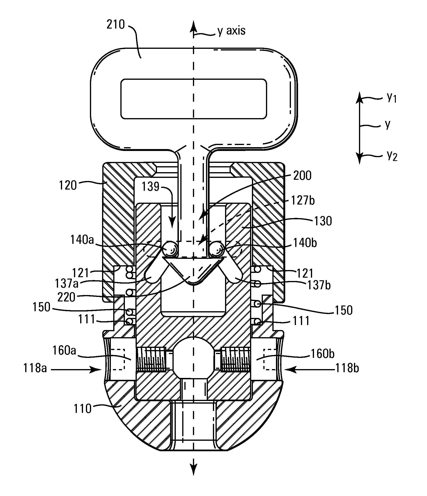
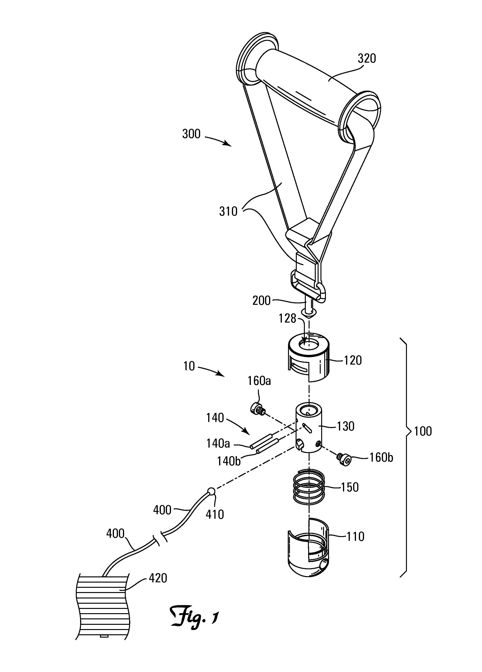
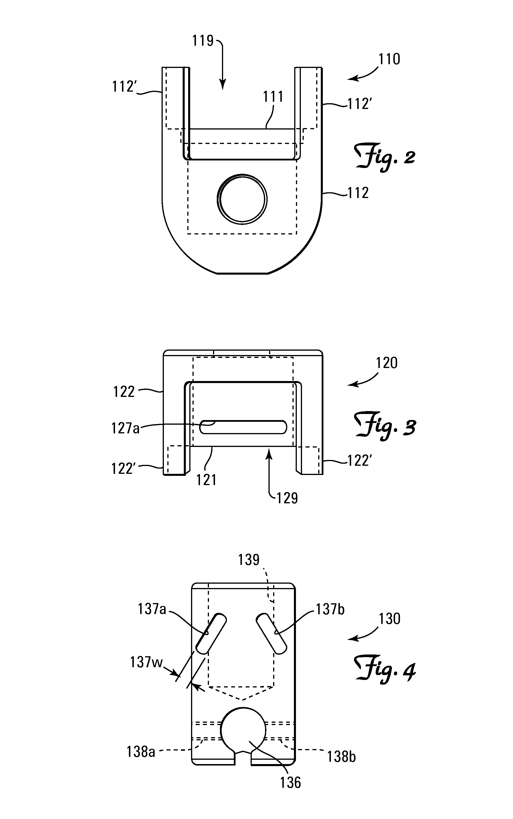
[0019]10 Quick Disconnect System[0020]100 Coupling[0021]110 Base[0022]111 Inner Annular Shoulder[0023]112 Sidewall[0024]112′ Sidewall Extensions[0025]118 Radial Orifices Through the Base[0026]118a First Radial Orifice Through the Base[0027]118b Second Radial Orifice Through the Base[0028]119 Chamber Defined by the Base[0029]120 Jacket[0030]121 Inner Annular Shoulder[0031]122 Sidewall[0032]122′ Sidewall Extensions[0033]127 Slots[0034]127a First Slot[0035]127b Second Slot[0036]128 Longitudinal Orifice Through the Jacket[0037]129 Chamber Defined by the Jacket[0038]130 Sleeve[0039]136 Cable End-Cap Retention Channel[0040]137 Tangential Channels Through the Sleeve[0041]137a First Tangential Channel Through the Sleeve[0042]137b Second Tangential Channel Through the Sleeve[0043]137w Width of Channel[0044]138 Threaded Radial Orifices In the Sleeve[0045]138a First Threaded Radial Orifice In the Sleeve[0046]138b Second Threaded Radial Orifice In the Sleeve[0047]139 Bore in Sleeve[...


PUM


Abstract

A quick disconnect system including a matable coupling and post. The coupling includes a base, a pair of pins, a jacket and a biasing means. The base defines a longitudinally extending bore. The pair of pins are radially repositionable relative to the bore and extend tangentially along opposite sides of the bore. The jacket cooperatively engages the base and the pins whereby longitudinal repositioning of the jacket as between a first stop position and a second stop position effects radial repositioning of the pins. The biasing means biases the jacket towards the first stop position. The post has a flanged head on the distal end of a shaft for cooperatively engaging the pins to achieve connection of the coupling and the post.

Description

[0001]This application claims the benefit of U.S. Provisional Application No. 60 / 820,975, filed Aug. 1, 2006.BACKGROUND[0002]Strength training equipment typically employs an exercise interface unit connected to a means of resistance, such as a weight stack or selecterizable series of leaf springs. Common exercise interface units include specifically, but not exclusively tricep straps, grip handles, tricep press down V bars, stirrup handles, chinning triangles, straight bars, double stirrup handles, curl bars, tricep ropes, straight lat bars, head harnesses, single cable handles, lat pull down bars, ankle cuffs, foot cuffs, and shoulder cuffs.[0003]It is often desirable to provide several different interchangeable exercise interface units for use with a single weight stack for purposes of increasing the versatility of the machine without significantly increasing the cost of the machine. While generally effective, experience has shown that users of such equipment tend to become frustr...

Claims


Application Information

Patent Timeline
Patent Type & Authority Patents(United States)
IPC IPC(8): B25G3/18F16B21/00F16D1/00
CPCA63B21/156A63B23/0355A63B21/062Y10T403/599A63B2210/10A63B2225/102Y10T403/592A63B2210/06A63B21/0628
Inventor CASSIDY, JOHN M.
Owner TORQUE FITNESS
Why Eureka
Try Eureka