Gondola with multi-part main shaft

a technology of gondola and main shaft, which is applied in the direction of mechanical equipment, machines/engines, electric generator control, etc., can solve the problems of manufacturing and transportation, and achieve the effects of improving the rotational rigidity of the shaft section, reducing material use, and improving the bending rigidity of the sha

Inactive Publication Date: 2013-08-13
SCHULER PRESSEN GMBH & CO KG
View PDF22 Cites 3 Cited by
  • Summary
  • Abstract
  • Description
  • Claims
  • Application Information

AI Technical Summary

Benefits of technology

[0010]This concept of a main shaft being divided between the two main bearings permits the manufacture of the main shaft or, respectively, the shaft sections by economical manufacturing methods. Preferably, the shaft sections are cast components which consist for example of cast iron or cast steel. This permits an optimization of the form of the main shaft with respect to the transmission of torque and with respect to bending moment stressing. For example the segments of the divided main shaft can be designed with respect to the shape thereof so as to accommodate the effective loads with minimal use of material and optimized in this regard. The segments or, respectively the shaft sections can be provided with internal longitudinal ribs which improve the bending rigidity of the shaft. Also spiral ribs may be provided to improve the rotational rigidity of the shaft sections. The shaft section arranged between the rotor hub and the first generator can be designed for a higher torque than the subsequent shaft section. The hollow shaft may also serve as servicing access to the hub interior. If necessary, a manhole may be provided in one of the shaft sections. Ribs extending around the manhole to prevent a weakening of this shaft section by the manhole.
[0011]The division of the main shaft into several shaft sections also facilitates the incorporation of several generators into the main shaft. For example a generator may be arranged at the end of the main shaft outside the two main bearings whereas another generator is arranged between the shaft sections of the main shaft and, consequently, is arranged between the main bearings of the gondola frame. This arrangement facilitates the generation of a large electric power output with comparatively small generators which can be handled relatively easily.
[0012]The concept furthermore facilitates the mounting of the gondola, the main shaft and the generators on a tower with reasonable expenditures. For example the shaft sections and the generators can be lifted onto the gondola frame and can be assembled there. The size of the components can be limited to a value at which, preassembled, they can still be transported. This results in obvious advantages and reduced costs for the manufacture, the transport and the assembly of the generators. For high power generators an overland-transport of the completed generators including the stator is made possible by the concept according to the invention.
[0013]Also, the electromagnetic forces and the deformations and vibrations initiated by the generators are easier to control in the smaller generators whose use is made possible by the invention. Furthermore, the use of several generators in one main shaft provides for a certain redundancy. Upon break-down of one generator the other generator or generators remain operable. The division of the main shaft makes an arrangement of two or more rotors in the main shaft possible in a simple manner. The rotors or respectively, the rotor shafts of the generators become parts of the main shaft. If two or more generators are provided, the torque path for driving of the generators more remote from the hub extends through rotors or rotor shafts of the generators closer to the hub.

Problems solved by technology

Wind power plants are often set up at remote locations and have substantial dimensions which may result in manufacturing and transportation problems.

Method used


Image

  • Gondola with multi-part main shaft
  • Gondola with multi-part main shaft
  • Gondola with multi-part main shaft

Examples


Embodiment Construction

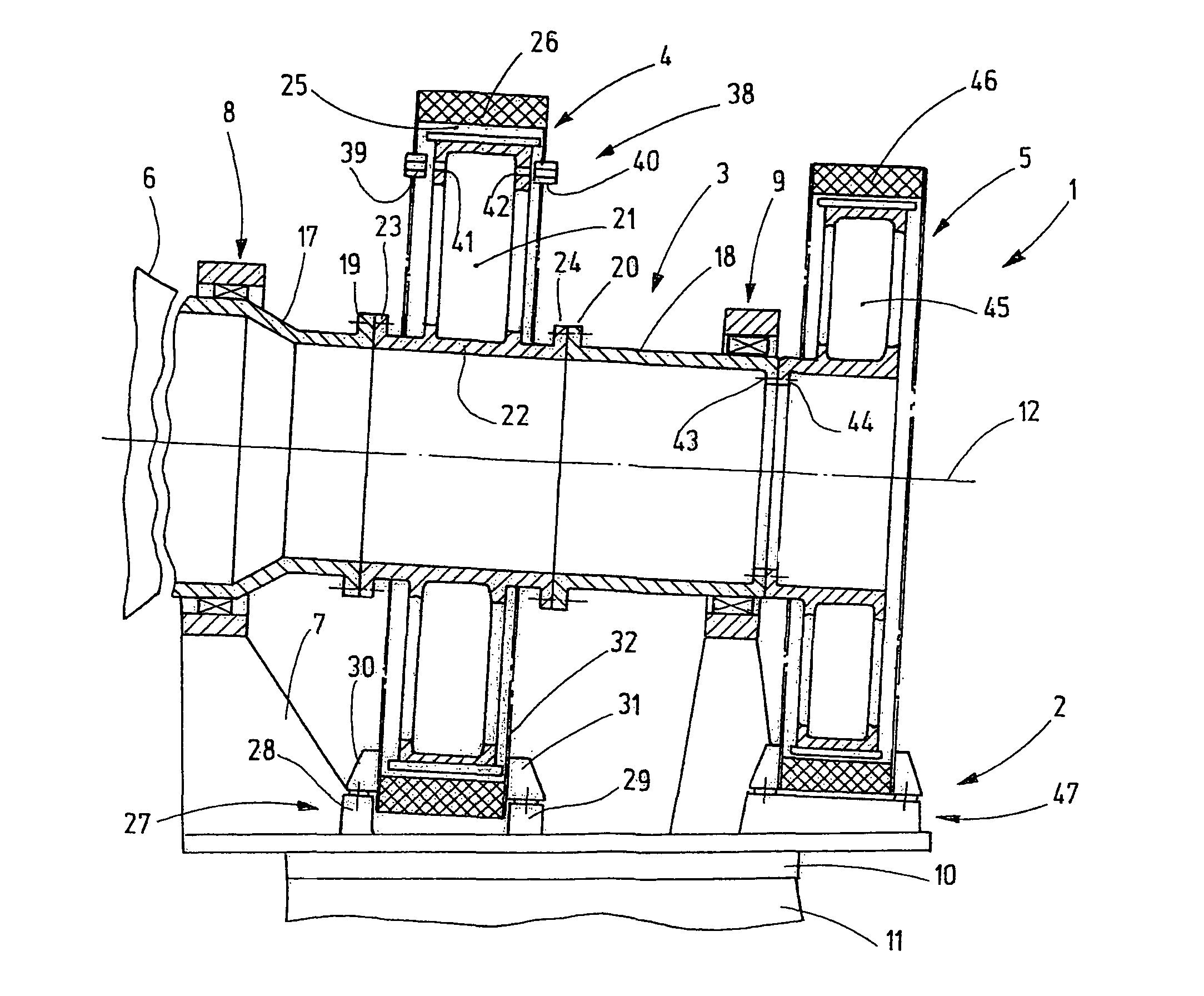
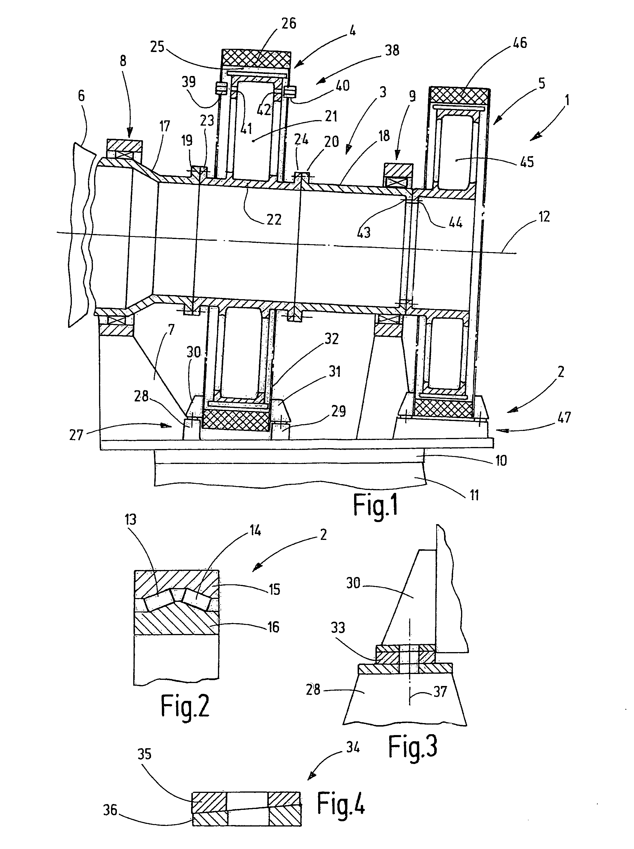
[0024]FIG. 1 shows a gondola 2 of a wind power plant 1, including a main shaft 3 and generators 4, 5. The main shaft 3 carries at one end thereof a hub 6 which is shown only schematically and which is provided with rotor blades so as to be rotated by wind.

[0025]The gondola 2 comprises a gondola frame 7 on which at least two main bearings are supported, rotationally supporting the main shaft 3. The gondola 2 is supported on an upper end of a tower 11 via a gondola bearing 10. The gondola bearing 10 has a vertical axis of rotation. The main bearings define an axis of rotation 12 which extends essentially horizontally or at an acute angle with respect to a horizontal direction.

[0026]The two main bearings 8, 9 are mounted at a certain support distance from each other so that at least one of the two generators 4, 5 can be arranged between the two main bearings 8, 9 as it is shown in FIG. 1. The main bearings are only schematically shown in FIG. 1. Preferably they are fixed-loose bearings...


PUM

PropertyMeasurementUnit
electric energyaaaaaaaaaa
diameteraaaaaaaaaa
dimensionsaaaaaaaaaa

Abstract

In the gondola (2) of a wind power plant (1) according to the invention the main shaft comprises several parts. The rotors (21, 45) of the generators (4, 5) are parts of the main shaft. Other shaft sections (17, 18) are used for supporting the main shaft (3) on the machine carrier or, respectively the gondola frame (7) and the attachment of the rotor hub (6). The generators (4, 5) may be completely pre-assembled and delivered as mounting units. During the pre-assembly of the generators, the rotor (21) and the stator (26) are fixed relative to one another by mounting aids. The mounting aids, interlocking devices, are removed after the whole drive train is mounted to the machine carrier (7).The stator of the generator (26) is mounted on the machine carrier (7) via adjustable supports.

Description

CROSS-REFERENCE TO RELATED APPLICATION[0001]This application claims the priority benefits of German Application No. 10 2009 015 926.6-15 filed Apr. 1, 2009.BACKGROUND OF THE INVENTION[0002]The invention concerns a gondola of a wind power plant for the generation of electricity.[0003]Wind power plants are often set up at remote locations and have substantial dimensions which may result in manufacturing and transportation problems. The designers therefore need to design the wind power plant in such a way that it operates reliably over long periods with little service requirements and that it can be manufactured and installed in an efficient manner.[0004]It is known to provide in wind power plants several generators which are all driven by a common main shaft.[0005]This is disclosed for example in DE 35 36 47. The wind power plant described therein comprises a gondola with a gondola frame in which a main shaft is rotatably supported by two bearings. Between the main bearings generators...

Claims


Application Information

Patent Timeline
Patent Type & Authority Patents(United States)
IPC IPC(8): F03D9/00
CPCF03D1/065F03D9/002F03D11/0008H02K7/1838F05B2240/14F05B2240/40F05B2240/50Y10T29/49009F05B2250/31H02K16/00Y02E10/721Y02E10/722Y02E10/725F05B2240/60F16C3/023F16C19/546F16C2360/31F03D9/25F03D13/20F03D80/70Y02E10/72Y02E10/728
Inventor LAUKE, ANDREAS
Owner SCHULER PRESSEN GMBH & CO KG
Why Eureka
Try Eureka