
Vehicle motion control device

a technology of motion control device and vehicle, which is applied in the direction of vehicle registration/indication, driver input parameters, gas pressure propulsion mounting, etc., can solve the problems of variable vibration of the vehicle, inability to properly and inability to accurately transmit the force to the road through the tires

Inactive Publication Date: 2013-08-13
DENSO CORP
View PDF39 Cites 13 Cited by
  • Summary
  • Abstract
  • Description
  • Claims
  • Application Information

AI Technical Summary

Benefits of technology

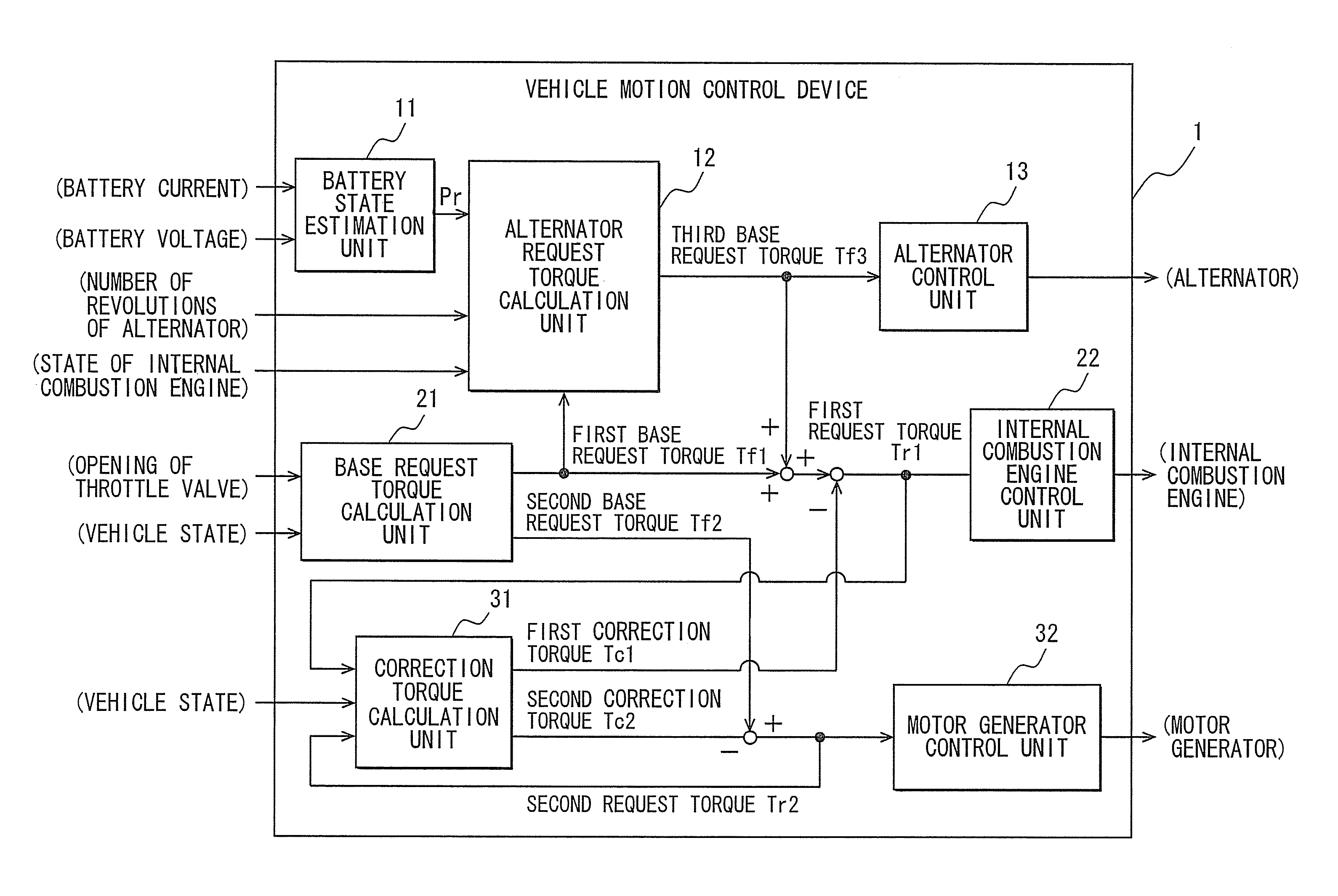
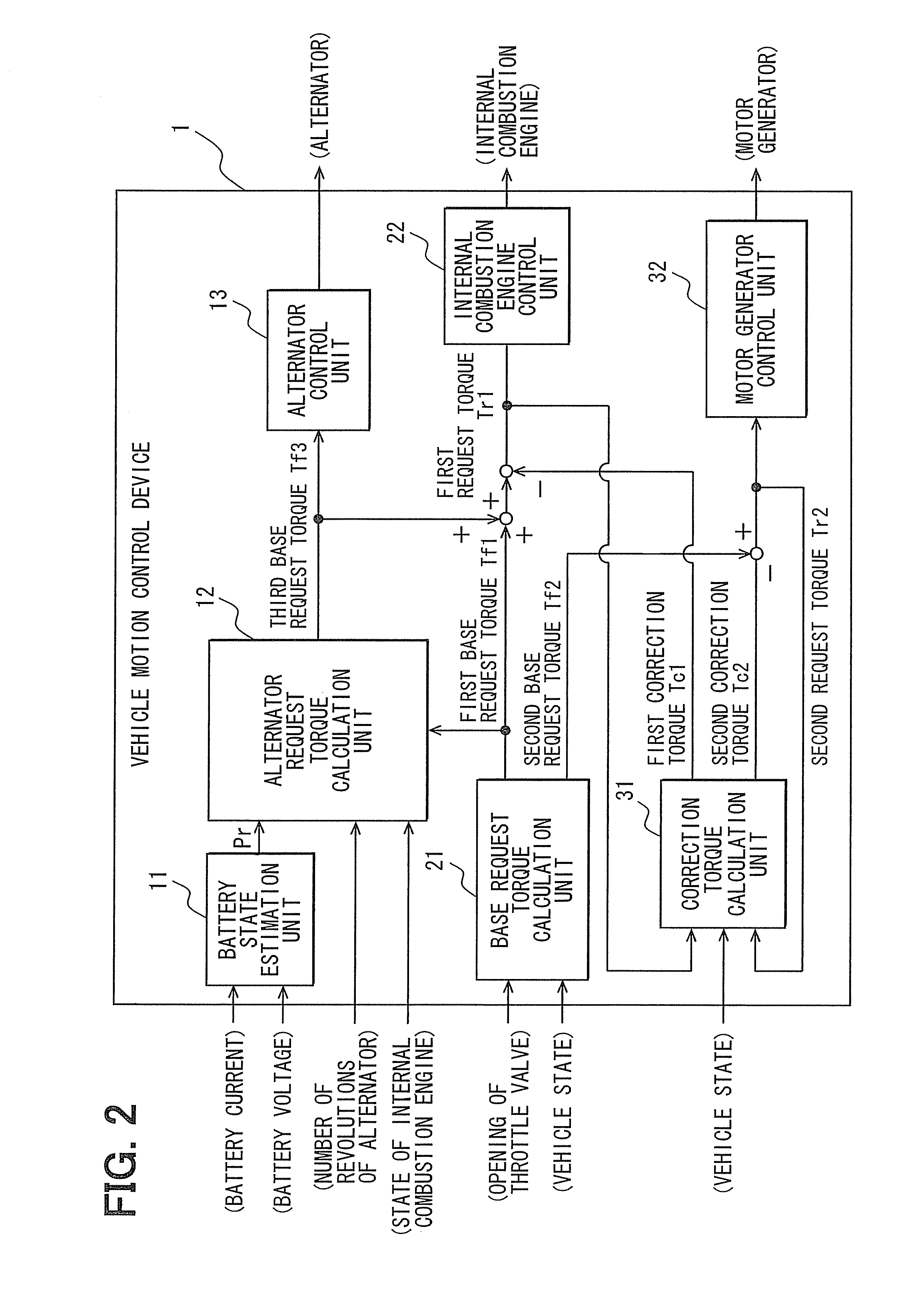
[0013]Further in accordance with various embodiments of the exemplary vehicle motion control device, the second base request torque corrected with the second correction torque is induced in a second output shaft. Herein, the second basis request torque is calculated in response to a request made by the driver of the vehicle, and the second correction torque is a compensated torque to be used to adjust natural vibrations in a high-frequency band of the vibrations of the components of the vehicle. The second base request torque corrected with the second correction torque is induced in the second output shaft using the second drive assembly including the motor generator. Consequently, the request of the driver can be met and the vibrations in the high-frequency band such as vibrations of tires can be increased, decreased or otherwise controlled.
[0014]Since the vibrations in the low-frequency band and in the high-frequency band are controlled, an oscillation associated with a load acting on the tires can be controlled. The contact state of the tires with a road and, correspondingly, the largest force to be transmitted to the road via the tires can be controlled. Consequently, the acceleration of the vehicle can be controlled. Through operation of the above described control, vehicle motion that meets the intention of the driver of the vehicle can be achieved.
[0016]Specifically, a first spring-mass model, in which vibrations of a vehicle body accommodating occupants are modeled, can be adopted as the low-frequency band model. The first drive assembly calculates the first correction torque for causing vibrations occurring in the first spring-mass model to adjust on the basis of the conditions of the vibrations occurring in the first spring-mass model. Consequently, the stability of the vehicle or the turning ability thereof can be controlled.
[0017]A second spring-mass model, in which vibrations associated with spring coupling between a chassis frame bearing a vehicle body, wheels joined to the chassis frame and vibrations of elastic tires coupled to wheels are modeled, should be adopted as the high-frequency band model. In such a case, the second drive assembly calculates the second correction torque for causing the vibrations occurring in the second spring-mass model to adjust on the basis of the conditions of the vibrations occurring in the second spring-mass model. The motion stability of the vehicle or the turning ability thereof can be further controlled.
[0018]In accordance with various embodiments, the four-wheel-drive vehicle advantageously includes a power storage means connected to the motor generator in order to feed power to the motor generator, and a generator that uses the torque of the first output shaft to generate power for charging the power storage means, and that offers a higher frequency response than the internal combustion engine. Consequently, the first base request torque can be readily corrected using the first correction torque.
[0021]When the amount of stored power of the power storage means falls below the reference value, the first control unit performs correction based on the first base request torque plus the third base request torque with a higher priority than performing correction based on the first base request torque plus the first correction torque. Consequently, the amount of stored power of the power storage means can be quickly restored.

Problems solved by technology

It is known that when a vehicle is accelerated, decelerated, or turned, various vibrations can occur in the vehicle.
When the unnecessary motion causes an oscillation in a load acting on tires, or especially, when the vehicle motion causes a body vibration in vertical direction, or during one of many other various factors causes unnecessary motion, vibration or movement, a problem arises as will be described in greater detail below.
However, if the load acting on the tires oscillates, a part of the force may not be transmitted to the road.
In such a situation, even when a torque can be faithfully induced in an output shaft via a drive assembly including an internal combustion engine or the like in response to a request made by a driver, the output may not be properly transmitted to the road via the tires and the acceleration of the vehicle may be disturbed.
Thus, the unnecessary motion may bring about a disturbance in the acceleration of the vehicle and vehicle motion meeting the intention of the driver becomes difficult to achieve.

Method used


Image

  • Vehicle motion control device
  • Vehicle motion control device
  • Vehicle motion control device

Examples


Embodiment Construction

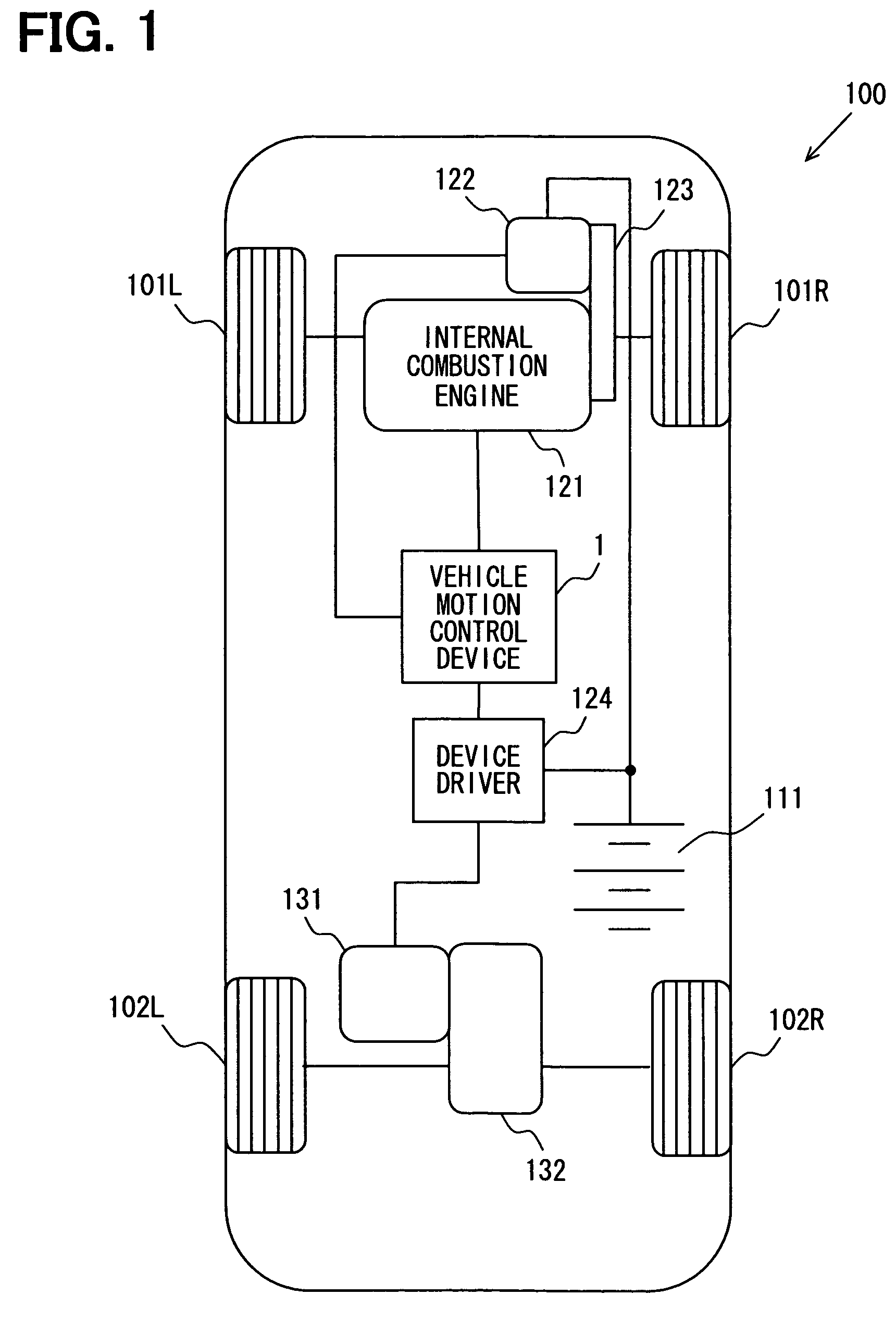
[0032]Referring to FIG. 1 to FIG. 8, an embodiment of a vehicle motion control device will be described below. FIG. 1 shows an example of the constitution of a vehicle in which the vehicle motion control device of the present embodiment is mounted. The vehicle will first be described.

[0033]A vehicle 100, as shown in FIG. 1, is a four-wheel-drive vehicle, and includes a battery 111 that can act as a power storage means, an internal combustion engine 121 that can act as a first drive assembly, an alternator 122 that can act as a generator or the first drive assembly, a motor generator 131 that can act as a motor, and a vehicle state detection means not specifically shown in FIG. 1.

[0034]The battery 111 is connected to and feeds power to drive various pieces of onboard equipment that are not specifically shown, the various pieces of onboard equipment. The battery 111 is connected to the alternator 122, which can act as a generator as will be described hereinafter, and power, in the for...


PUM


Abstract

A vehicle motion control device adjusts vibrations occurring in components of a vehicle so as to control the motion of a vehicle having independent drive assemblies for front wheels and for rear wheels. The vehicle motion control device includes a base request torque calculation unit that calculates first and second base request torques in response to a request made by the driver of a vehicle. A correction torque calculation unit calculates first and second correction torques used to adjust vibrations in a low-frequency band and in a high-frequency band of the vibrations of the components of the vehicle. An internal combustion engine control unit and a motor generator control unit control an internal combustion engine and a motor generator so that the first and second base request torques are corrected with the first and second correction torques.

Description

CROSS REFERENCE TO RELATED APPLICATIONS[0001]The present application is based on and claims priority to Japanese Patent Application No. 2007-321222, filed on Dec. 12, 2007, the entire contents of which are incorporated herein by reference.BACKGROUND OF THE INVENTION[0002]1. Field of the Invention[0003]The present invention relates to a vehicle motion control device and more specifically to a control device mounted in a four-wheel-drive vehicle having independent front wheel and rear wheel drive assemblies.[0004]2. Description of the Related Art[0005]It is known that when a vehicle is accelerated, decelerated, or turned, various vibrations can occur in the vehicle. Specifically, when a vehicle driver provides a motion command to the vehicle, for example by depressing the accelerator pedal, unnecessary motion of a vehicle body, such as a pitching motion, a vertical motion, or vibrations of tires can be made by the vehicle in addition to a motion associated with the running command.[00...

Claims


Application Information

Patent Timeline
Patent Type & Authority Patents(United States)
IPC IPC(8): G06F17/00B60K6/20B60K6/52G06F19/00
CPCB60K6/48B60W10/06B60W10/08B60W30/045B60W30/20B60L11/123B60L11/14B60L11/1861B60L15/20B60K6/52Y02T10/642B60L2240/441B60W20/00B60W2510/0638B60W2540/10B60W2710/0666B60W2720/30Y02T10/6221Y02T10/6265Y02T10/6286B60L2240/421B60L2240/423B60L2240/443B60L2240/547B60L2240/549B60L2260/28B60L2260/44B60L2270/145Y02T10/7077Y02T10/7044Y02T10/7005Y02T10/705Y02T10/7275Y02T10/6217B60W2540/18B60L50/16B60L50/61B60L58/12Y02T10/62Y02T10/64Y02T10/70Y02T10/7072Y02T10/72B60W40/10B60W20/11
Inventor MORI, KATSUYUKISAWADA, MAMORUMATSUMOTO, TOSHIKISADA, TAKESHI
Owner DENSO CORP
Learn More