Method of forming a golf club head with improved aerodynamic charcteristics

a golf club and aerodynamic technology, applied in the field of golf club heads with aerodynamic charcteristics, can solve the problems of failing to provide drivers with designs, usga has increasingly limited the performance innovations of golf clubs, particularly drivers, and usga has limited the volume and dimensions of the head, so as to improve the aspect ratio improve the crown surface design of the driver club, and improve the effect of the driver club head

Active Publication Date: 2013-08-20
TOPGOLF CALLAWAY BRANDS CORP
View PDF12 Cites 5 Cited by
  • Summary
  • Abstract
  • Description
  • Claims
  • Application Information

AI Technical Summary

Benefits of technology

[0011]The main objective of the present invention is to improve the aspect ratio of the driver club head and to improve driver club head crown surface design. To improve the aspect ration of the driver club head, a driver is created which has an increased depth, distance from the face to the most rearward point, while reducing the overall height. This design will improve air flow over the face and crown of the driver and minimize the overall projected area of the club head in the direction of the air flow. Improvements on the driver club head crown surface design include creating a driver having a crown surface that is flatter, less curvature, while combining it with an apex point location that is further away from the face to promote a more preferred air flow over the club head.

Problems solved by technology

The prior art fails to provide a driver with designs that efficiently reduce drag forces and consequentially enable the driver to be swung faster along its path and contribute to an improved impact event with the golf ball.
The United States Golf Association (USGA) has increasingly limited the performance innovations of golf clubs, particularly drivers.
Recently, the USGA has limited the volume, dimensions of the head, such as length, width, and height, face compliance, inertia of driver heads and overall club length.
Current methods previously used to improve the performance of a driver have been curtailed by limitations on design parameters set by the USGA.
However, these recent trends may also be detrimental to the driver's performance due to the head speed reductions that these design features introduce due to the larger geometries.

Method used


Image

  • Method of forming a golf club head with improved aerodynamic charcteristics
  • Method of forming a golf club head with improved aerodynamic charcteristics
  • Method of forming a golf club head with improved aerodynamic charcteristics

Examples


Embodiment Construction

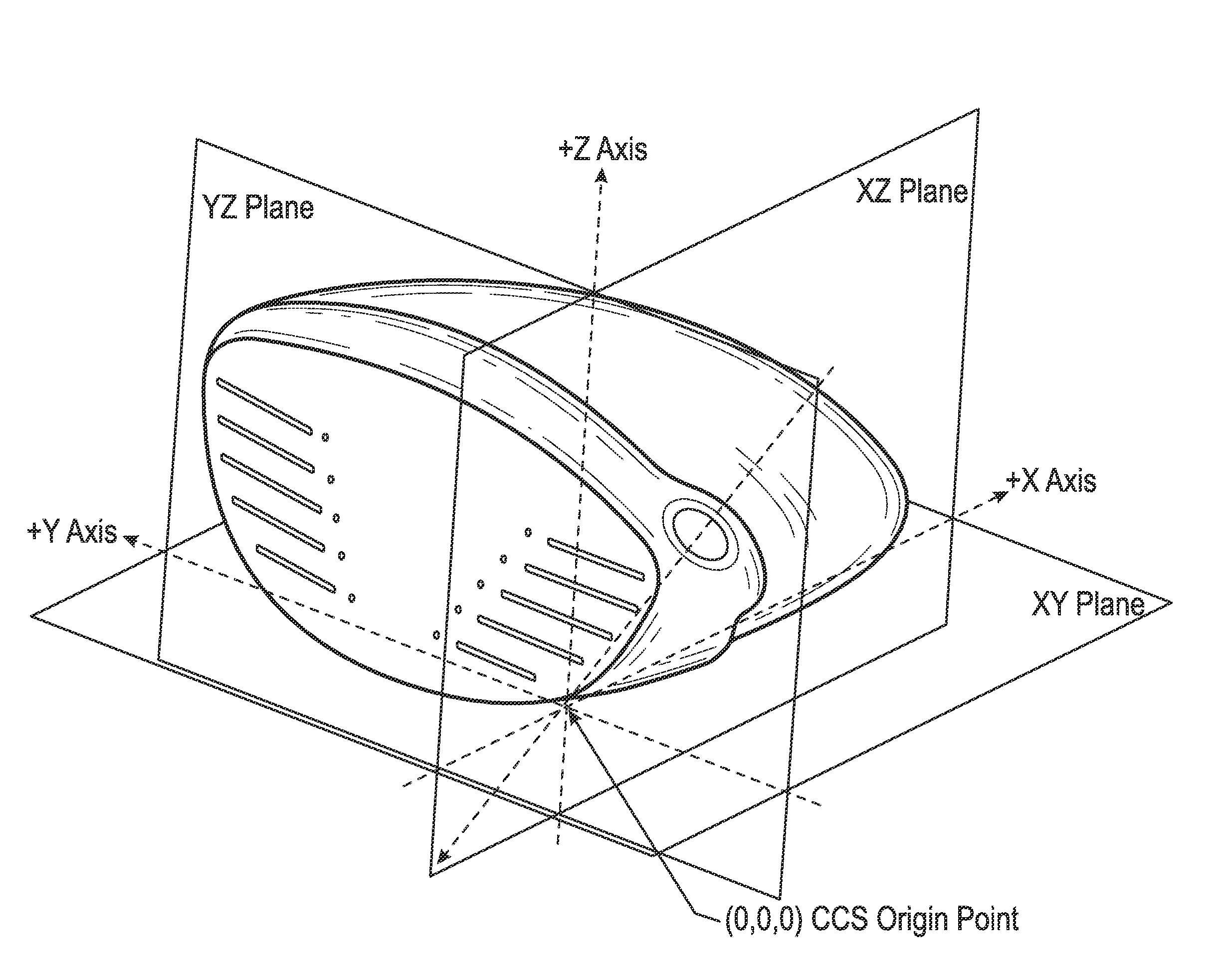
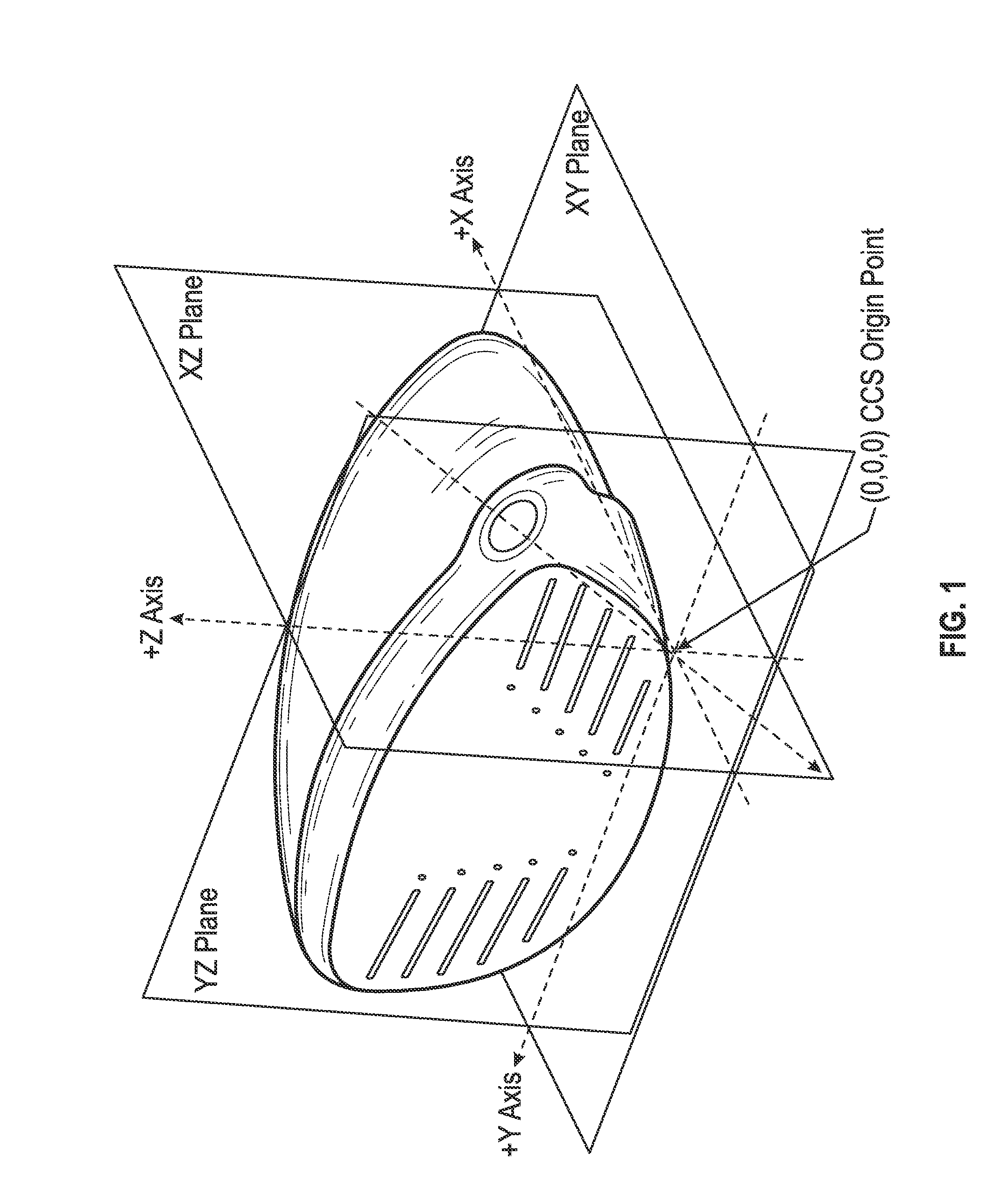
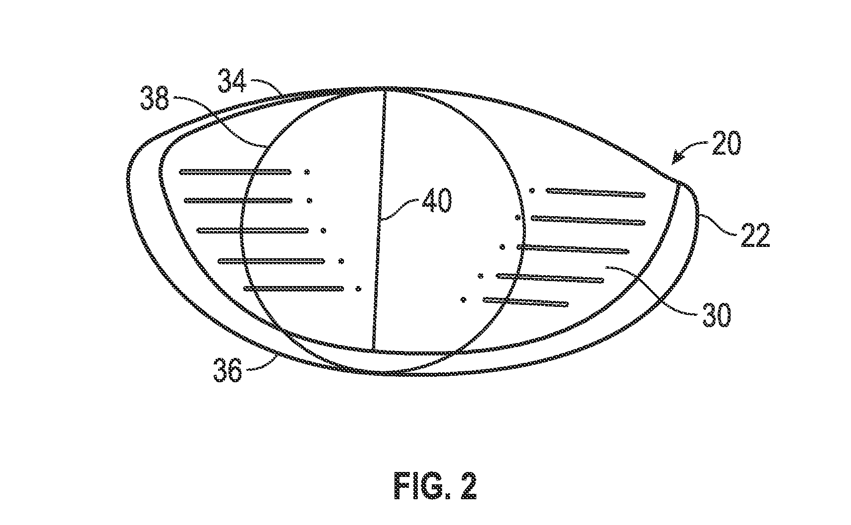
[0025]The present invention relates to the design relationships and methods of measurement comprising the improved aspect ratio of the driver golf club head 20 and the improved driver golf club head 20 crown 26 surface design. To verify the existence of conforming or non-conforming geometries of a driver club head 20, a method of measurement has been developed called the, “Largest Tangent Circle Method (LTCM)”.

[0026]In a preferred embodiment of the present invention, the method for forming a driver type golf club head 20 comprises placing the club head 20 into a Cartesian Coordinate System (CCS) comprising a X axis, a Y axis, and a Z axis, wherein three perpendicular planes exists. The three perpendicular planes are XY, YZ and XZ, and the three perpendicular planes intersect at an origin point. The club head 20 comprises a body 22, a hosel 24, a crown 26, a sole 25 and a face 30. The hosel axis line 32 of the club head 20 is oriented in the YZ plane passing through the origin point....


PUM

PropertyMeasurementUnit
lengthaaaaaaaaaa
heightaaaaaaaaaa
heightaaaaaaaaaa

Abstract

A method of forming a golf club head having improved aerodynamic characteristics. The method comprises a largest tangent circle method utilizing a cartesian coordinate system. The method results in the highest point of the crown surface located within a crown apex zone, wherein this location aids in the improved aerodynamic properties of the golf club head.

Description

CROSS REFERENCES TO RELATED APPLICATIONS[0001]This application claims priority to U.S. Provisional Patent Application No. 61 / 303,161 filed on Feb. 10, 2010.STATEMENT REGARDING FEDERALLY SPONSORED RESEARCH OR DEVELOPMENT[0002]Not ApplicableBACKGROUND OF THE INVENTION[0003]1. Field of the Invention[0004]The present invention relates to a method for reducing the effects of drag force when using a driver.[0005]2. Description of the Related Art[0006]The prior art discloses various designs to reduce the drag force to improve driver performance.[0007]The prior art fails to provide a driver with designs that efficiently reduce drag forces and consequentially enable the driver to be swung faster along its path and contribute to an improved impact event with the golf ball.[0008]The United States Golf Association (USGA) has increasingly limited the performance innovations of golf clubs, particularly drivers. Recently, the USGA has limited the volume, dimensions of the head, such as length, wid...

Claims


Application Information

Patent Timeline
Patent Type & Authority Patents(United States)
IPC IPC(8): B23P15/00
CPCA63B53/0466A63B2053/0408A63B2053/0412Y10T29/49764A63B2225/01A63B2053/0437A63B2059/0011A63B53/0412A63B53/0408A63B53/0437A63B60/006
Inventor EVANS, D. CLAYTONGIBBS, EVAN D.CACKETT, MATTHEW T.EHLERS, STEVEN M.
Owner TOPGOLF CALLAWAY BRANDS CORP
Why Eureka
Try Eureka