Accessory mounting structure

a technology of accessory mounting and mounting structure, which is applied in the direction of machine/engine, machine frame, casing, etc., can solve the problems of increasing work efficiency, reducing the accuracy of bolt holes, and requiring a lot of labor, so as to achieve stably held, simple structure, and increased work efficiency in turning accessories for positioning.

Active Publication Date: 2013-08-20
MITSUBISHI MOTORS CORP
View PDF6 Cites 9 Cited by
  • Summary
  • Abstract
  • Description
  • Claims
  • Application Information

AI Technical Summary

Benefits of technology

[0011]The present invention has been accomplished in light of the above-described situations. It is an object of the invention to provide an accessory mounting structure which can mount an accessory on a cylinder block of a vehicle engine with satisfactory work efficiency while keeping support accuracy high.
[0013]According to the first aspect of the invention, the shank of the bolt fastening the mounting piece is inserted into the horizontal groove from the lateral direction toward the cylinder block, and the movement of the bolt toward the opening of the horizontal groove is restrained. Thus, during mounting work for the accessory, the labor of lifting the accessory for insertion of the bolt into the horizontal groove is lessened. Further, after the insertion of the bolt, the weight of the accessory is borne within the horizontal groove. Hence, the accessory is held stably, and the labor of supporting the accessory is lessened, thus facilitating the works of positioning and fixing the accessory.
[0014]Consequently, the accessory can be mounted on the cylinder block of the vehicle engine with good work efficiency and with support accuracy kept high.
[0016]According to the second aspect of the invention, the accessory is turned about the axis of the bolt to position the upper side of the accessory. Thus, the accessory, if heavy, can be easily positioned.
[0018]According to the third aspect of the invention, during the mounting work for the accessory, the fixing portion is located ahead of the horizontal groove. Thus, the work efficiency in turning the accessory for positioning is further increased. As noted here, the fixing portion is located forwardly of the horizontal groove, and the shank of the bolt is borne by the lower surface of the horizontal groove. Thus, the accessory is turned about the fixing portion as a fulcrum, so that the shank of the bolt does not escape from the horizontal groove. Since the shank of the bolt is borne nearly uniformly along the lower surface of the horizontal groove, the accessory is stably held, and the simple structure can further improve the support accuracy of the accessory.
[0019]The accessory mounting structure according to the present invention can mount the accessory on the cylinder block of the vehicle engine with satisfactory work efficiency and with support accuracy kept high.

Problems solved by technology

Thus, much labor is required.
This technology, therefore, does not necessarily result in an increased work efficiency.
Furthermore, a heavy weight is put on bolt holes at a site where the alternator is fixed, and repeated insertion and removal of the bolt for replacement or maintenance of the alternator may decrease the accuracy of the bolt holes.
As a result, it may be difficult to maintain the alternator at the predetermined position with high accuracy, and the coplanarity of the pulley of the alternator and the pulley of the crankshaft may fail to be kept.

Method used


Image

  • Accessory mounting structure
  • Accessory mounting structure
  • Accessory mounting structure

Examples


Embodiment Construction

[0029]An embodiment of the present invention will be described in detail with reference to the accompanying drawings.

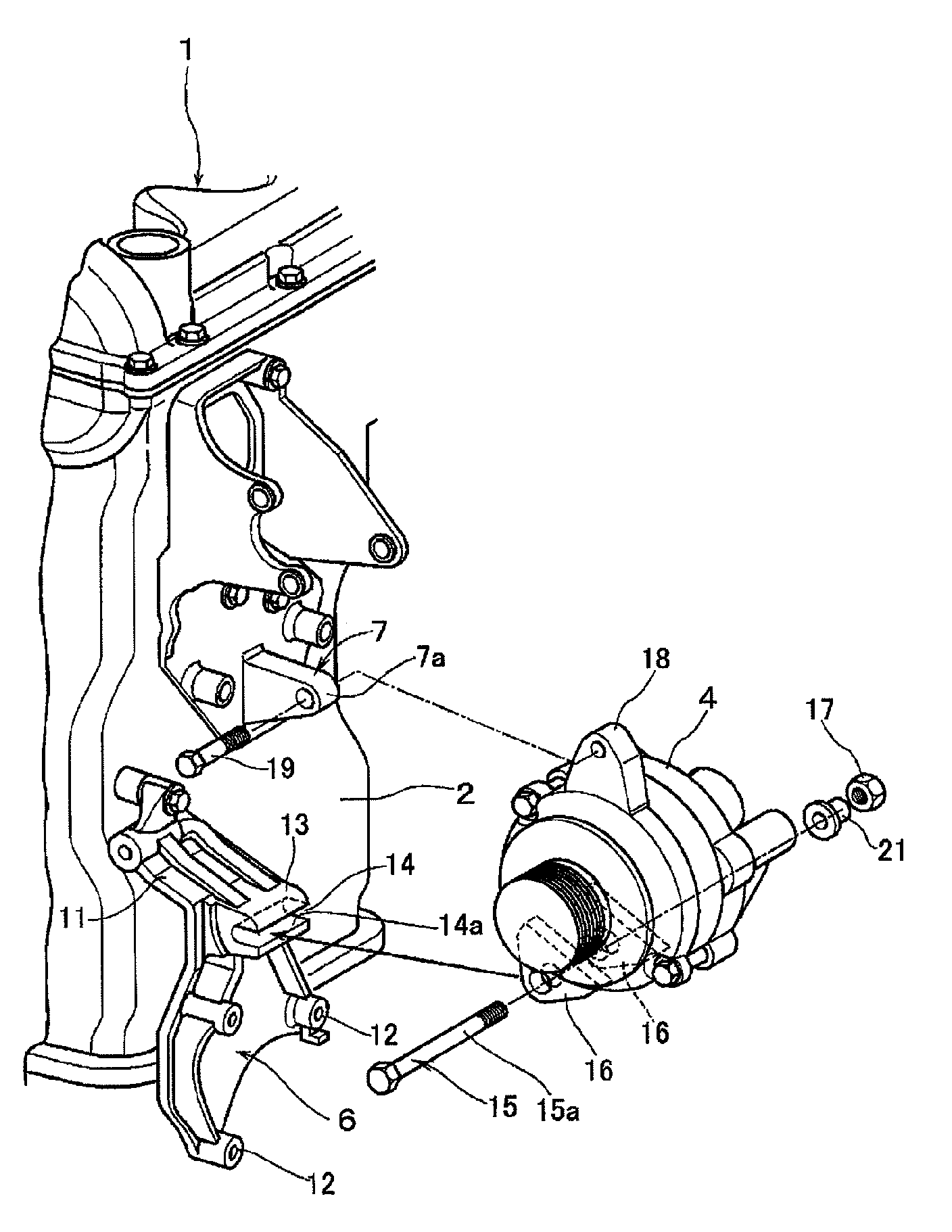
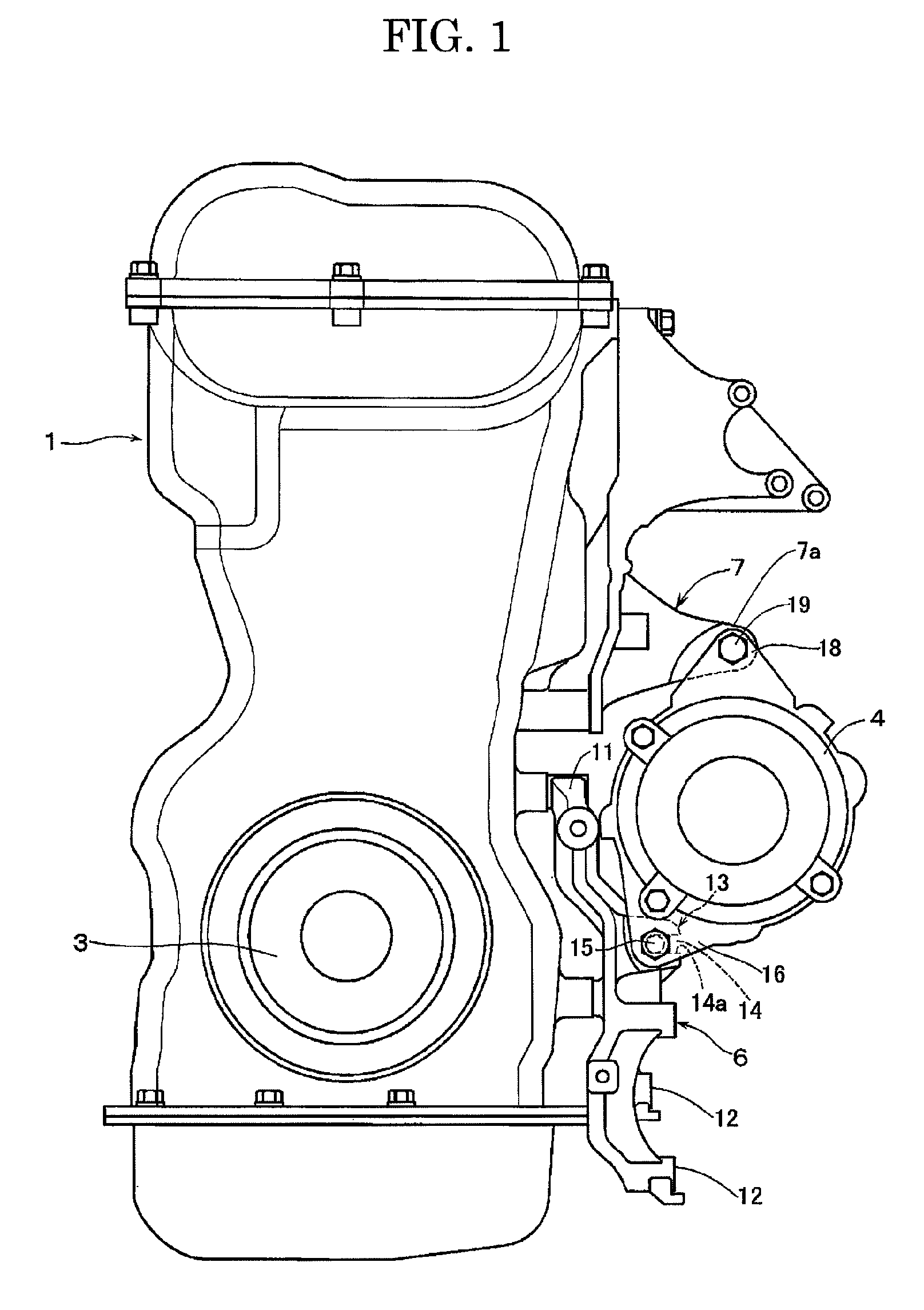
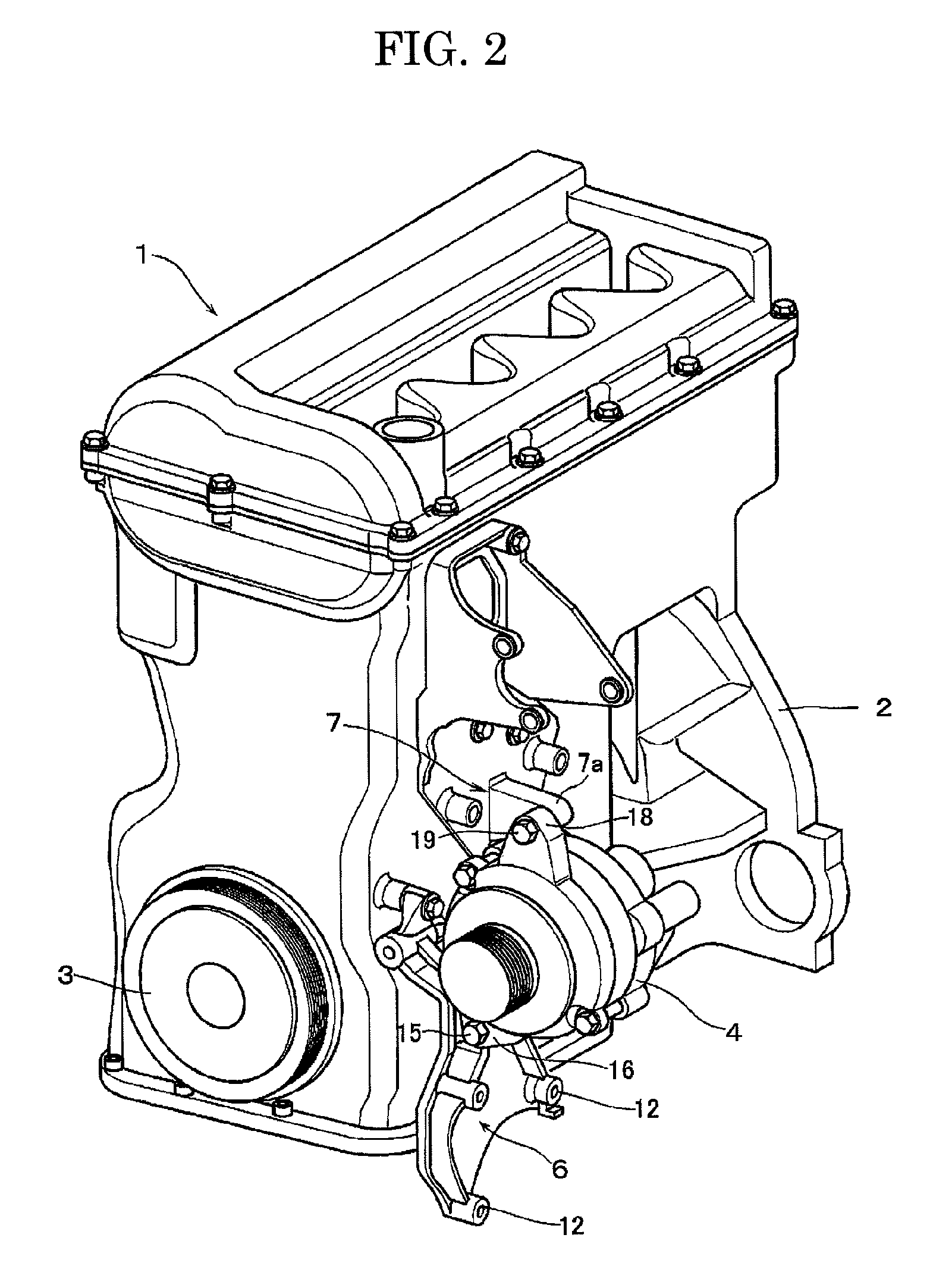
[0030]As shown in FIGS. 1 and 2, a vehicle engine (engine) 1 is an in-line multi-cylinder engine, and a crankshaft pulley 3 connected to a crankshaft is disposed at the front of a cylinder block 2 of the engine 1. On the other hand, an alternator 4 is held, as an accessory, beside the side surface of the cylinder block 2. Further, a power steering pump and an air compressor are held beside the side surface of the cylinder block 2.

[0031]A pulley of an accessory, such as the alternator 4, is disposed on the same plane as the crankshaft pulley 3, and a belt is looped over the crankshaft pulley 3 and the pulley of the accessory via an idler pulley and a tension pulley. By so doing, the drive force of the crankshaft of the engine 1 is transmitted to the accessory such as the alternator 4.

[0032]As shown in FIGS. 1 to 5, an alternator bracket 6 as an accessory mounting brack...


PUM


Abstract

A horizontal groove extending horizontally when an alternator bracket is fixed to a cylinder block of a vehicle engine is formed in the alternator bracket. A shank of a bolt inserted through mounting pieces of an alternator is inserted into the horizontal groove from a horizontally lateral direction toward the cylinder block to support the bolt on a lower surface of the horizontal groove. After insertion, the bolt is restrained from moving toward an opening of the horizontal groove. Since the insertion of the bolt into the horizontal groove is facilitated, and the weight of the alternator is borne by the lower surface of the horizontal groove, a burden on a fixing portion is reduced, and it becomes easy to position the alternator and hold it when it is fixed. Thus, the accessory can be mounted on the cylinder block with satisfactory work efficiency and with support accuracy kept high.

Description

[0001]The entire disclosure of Japanese Patent Application No. 2007-329144 filed Dec. 20, 2007 is expressly incorporated by reference herein.BACKGROUND OF THE INVENTION[0002]1. Field of the Invention[0003]This invention relates to a mounting structure for an accessory which is mounted on a vehicle engine.[0004]2. Description of the Related Art[0005]A vehicle engine is mounted with accessories such as an alternator, a power steering pump, and an air compressor. The accessories are driven by the rotating power of a crankshaft of the vehicle engine which is transmitted via a V-ribbed belt or a V-grooved belt, a pulley, etc. Thus, the accessories are positioned and held on a cylinder block of the vehicle engine so that the pulley of the crankshaft and the pulleys of the accessories will be held within the same plane.[0006]The accessories such as the alternator are held on the cylinder block of the vehicle engine via accessory mounting brackets. That is, the accessory mounting brackets a...

Claims


Application Information

Patent Timeline
Patent Type & Authority Patents(United States)
IPC IPC(8): F02B67/00
CPCF02B67/00F02F7/0068F02B67/06F02B67/04
Inventor KOYAMA, KAZUAKIHORI, SUMITOMATSUI, SATOSHI
Owner MITSUBISHI MOTORS CORP
Why Eureka
Try Eureka