
Coaxial electric connector

a technology of electric connectors and coaxial cables, which is applied in the direction of coupling devices, electrical devices, two-part coupling devices, etc., can solve the problems of easy deformation of the position or balance of the electric connector in the mating operation, difficult mutual mating alignment between the two connectors, etc., and achieves positional stability upon mating mutually, smooth insertion, and stably and precisely carried out

Inactive Publication Date: 2013-08-20
DAIICHI SEIKO CO LTD
View PDF4 Cites 9 Cited by
  • Summary
  • Abstract
  • Description
  • Claims
  • Application Information

AI Technical Summary

Benefits of technology

The present invention provides a coaxial electric connector with a simple configuration that allows for easy and precise mating between connectors. The connector has an insertion reference surface on the inner-side contact, which helps to smoothly insert the outer-side contact and maintain stable and precise mating with low insertion force. This prevents inclined mating and improves the mating state and electrical contact state between the connectors. The connector also ensures a good mating state and prevents detachment or removal of the connectors. Additionally, the connector has an insulating housing with improved strength and durability for reliable mating operations. Overall, the invention provides an improved and reliable coaxial electric connector at a low cost.

Problems solved by technology

However, when downsizing and height-reduction are carried out, the alignment upon mating mutually between both the connectors becomes difficult.
Therefore, there are problems that load in the mating operation is increased, and the position or the balance of the electric connector in the mating operation easily becomes defective.

Method used


Image

  • Coaxial electric connector
  • Coaxial electric connector
  • Coaxial electric connector

Examples


Embodiment Construction

[0026]Hereinafter, embodiments of the present invention will be explained in detail based on drawings.

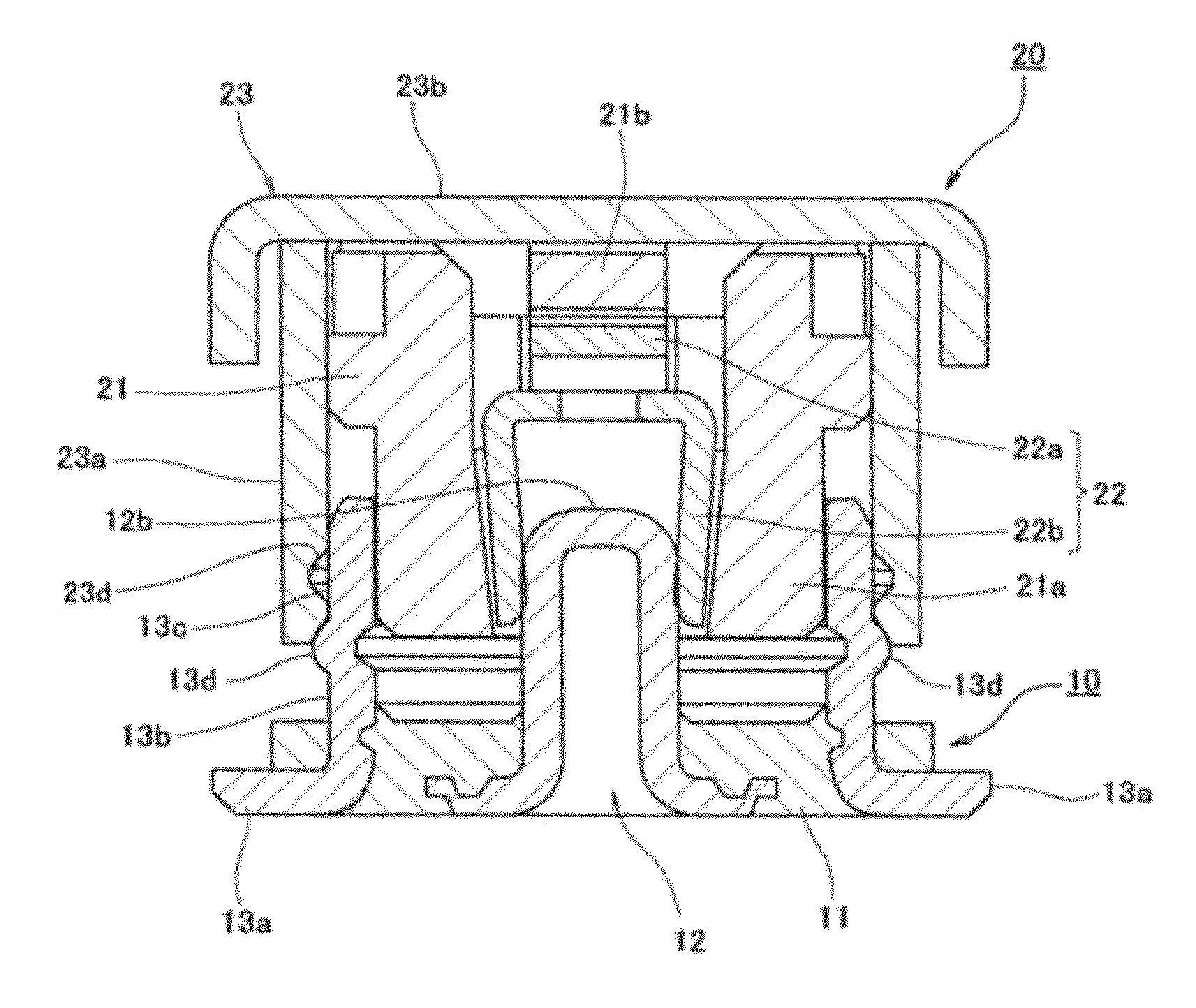
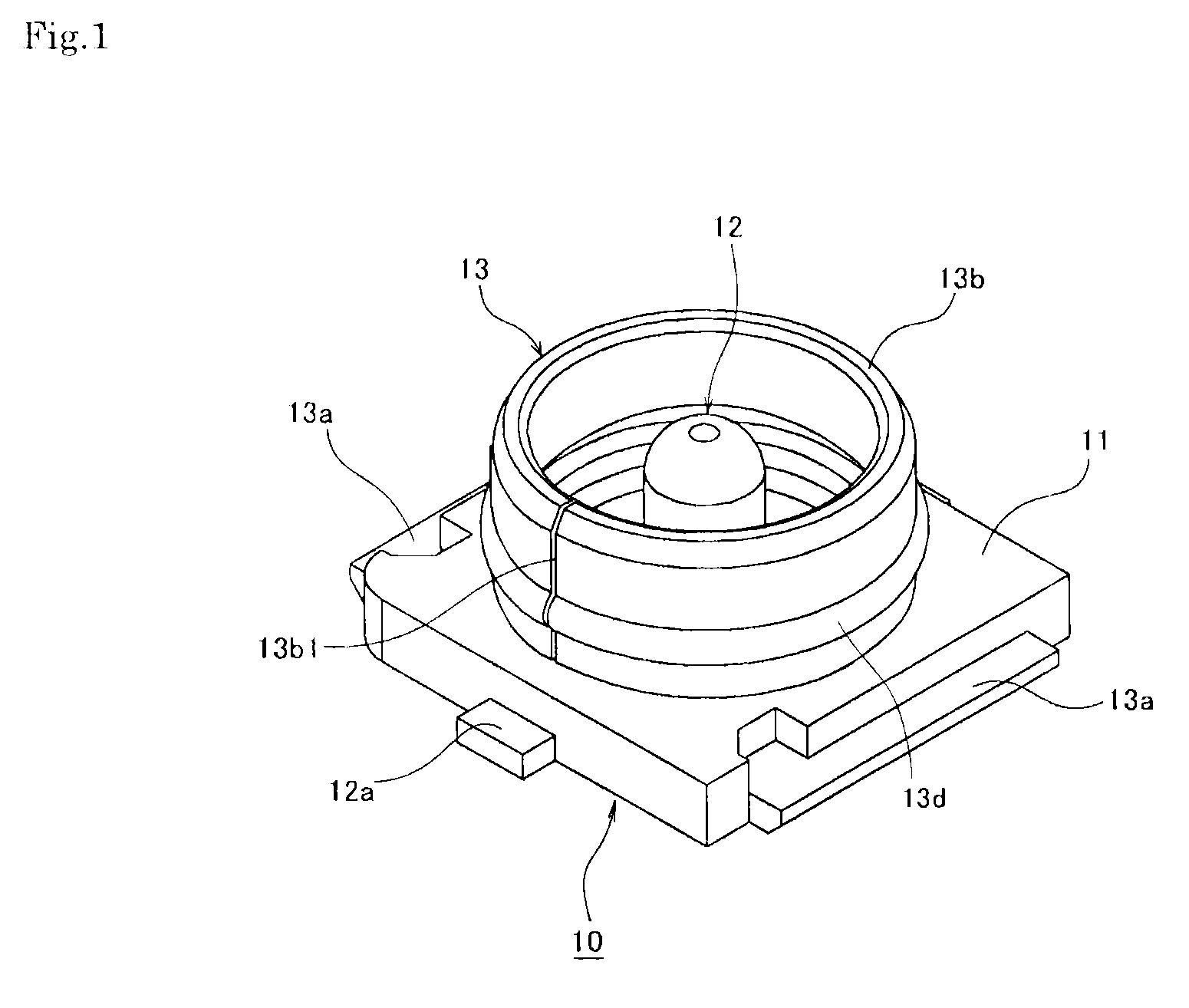
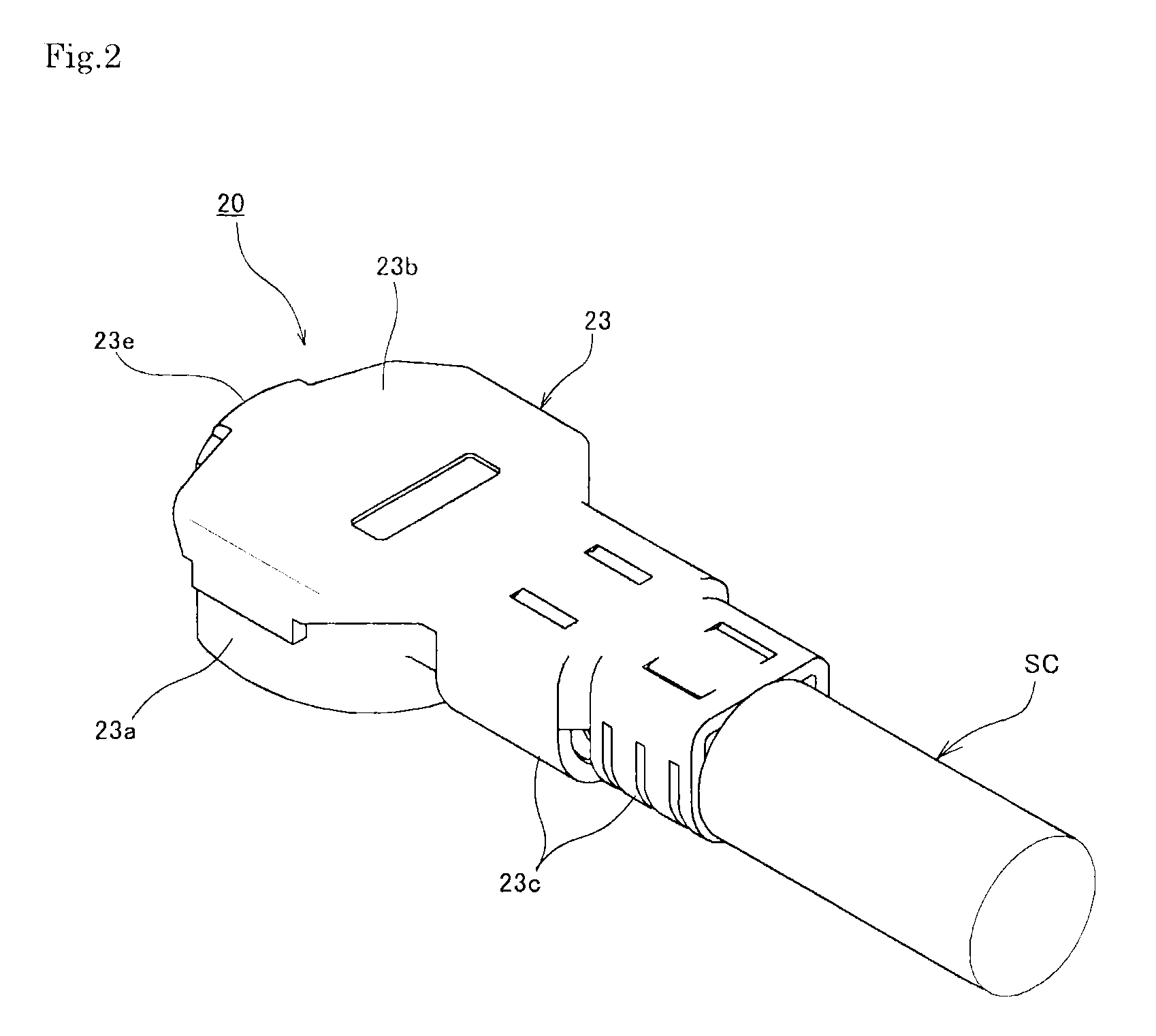
[0027]First, the assembly of a coaxial electric connector according to a first embodiment of the present invention shown in FIG. 1 to FIG. 6 is composed of a receptacle connector 10 (see FIG. 1) of a vertical-mating type mounted on a printed wiring board (illustration omitted) and a plug connector 20 (see FIG. 2) serving as an opposing connector thereof. With respect to the receptacle connector 10, the plug connector 20 can be mated from the upper side or removed. Hereinafter, the mating direction of inserting the plug connector 20 into the receptacle connector 10 will be referred to as “downward direction”, and the opposite removing direction of removing that will be referred to as “upward direction”.

[About Receptacle Connector]

[0028]The receptacle connector 10 constituting one of mating bodies of such a coaxial electric connector is provided with an insulating housing (dielectric ...


PUM


Abstract

A mating operation mutually between connectors can be easily and precisely carried out with a simple configuration. An insertion reference surface having a predetermined outer-diameter size D1 is provided to extend by a predetermined length in an axial direction on an outer peripheral surface of an inner-side contact among both cylindrical-shaped contacts overlapped with each other in inside / outside in the radial direction. A mutual mating relation is set so that the inner peripheral surface of the outer-side contact has an inner-diameter size D2 (D2≈D1) approximately same as an outer-diameter size D1 of the insertion reference surface of the inner-side contact. The outer-side contact can be smoothly inserted while carrying out positioning by the insertion reference surface of the inner-side contact 13.

Description

BACKGROUND OF THE INVENTION[0001]1. Field of the Invention[0002]The present invention relates to a coaxial electric connector configured so that cylindrical contacts are mutually mated / removed.[0003]2. Description of the Related Art[0004]Generally, in various electric devices, etc., electric connectors for electrically connecting various signal transmitting media such as coaxial cables are widely used. For example, in a coaxial electric connector shown in FIG. 9, a plug connector 2 to which a terminal part of a coaxial cable serving as a signal transmitting medium (see a symbol SC in FIG. 2 showing the present invention) is coupled is configured to be able to be mated / removed in the top-bottom direction of the drawing with respect to a receptacle connector 1 mounted and used on a printed wiring board. Among them, in the receptacle connector 1, a center contact 1b for signal transmission and an external contact 1c for grounding are approximately-concentrically attached to a plate-lik...

Claims


Application Information

Patent Timeline
Patent Type & Authority Patents(United States)
IPC IPC(8): H01R9/05
CPCH01R24/50H01R13/631H01R13/6277H01R2103/00H01R9/05
Inventor TAKANO, TOMOHITOMINEGISHI, HIDENORI
Owner DAIICHI SEIKO CO LTD
Learn More