
Integrated circulators sharing a continuous circuit

a circulator and continuous circuit technology, applied in the field of devices and systems, can solve the problems of discontinuities between the circulator and the circuit trace, degrading the electrical performance of the circulator, and adding complexity to the manufacturing process, so as to overcome the performance loss, reduce the manufacturing cost of printed circuit boards, and eliminate impedance mismatches

Active Publication Date: 2013-08-20
EMS TECHNOLOGIES
View PDF33 Cites 6 Cited by
  • Summary
  • Abstract
  • Description
  • Claims
  • Application Information

AI Technical Summary

Benefits of technology

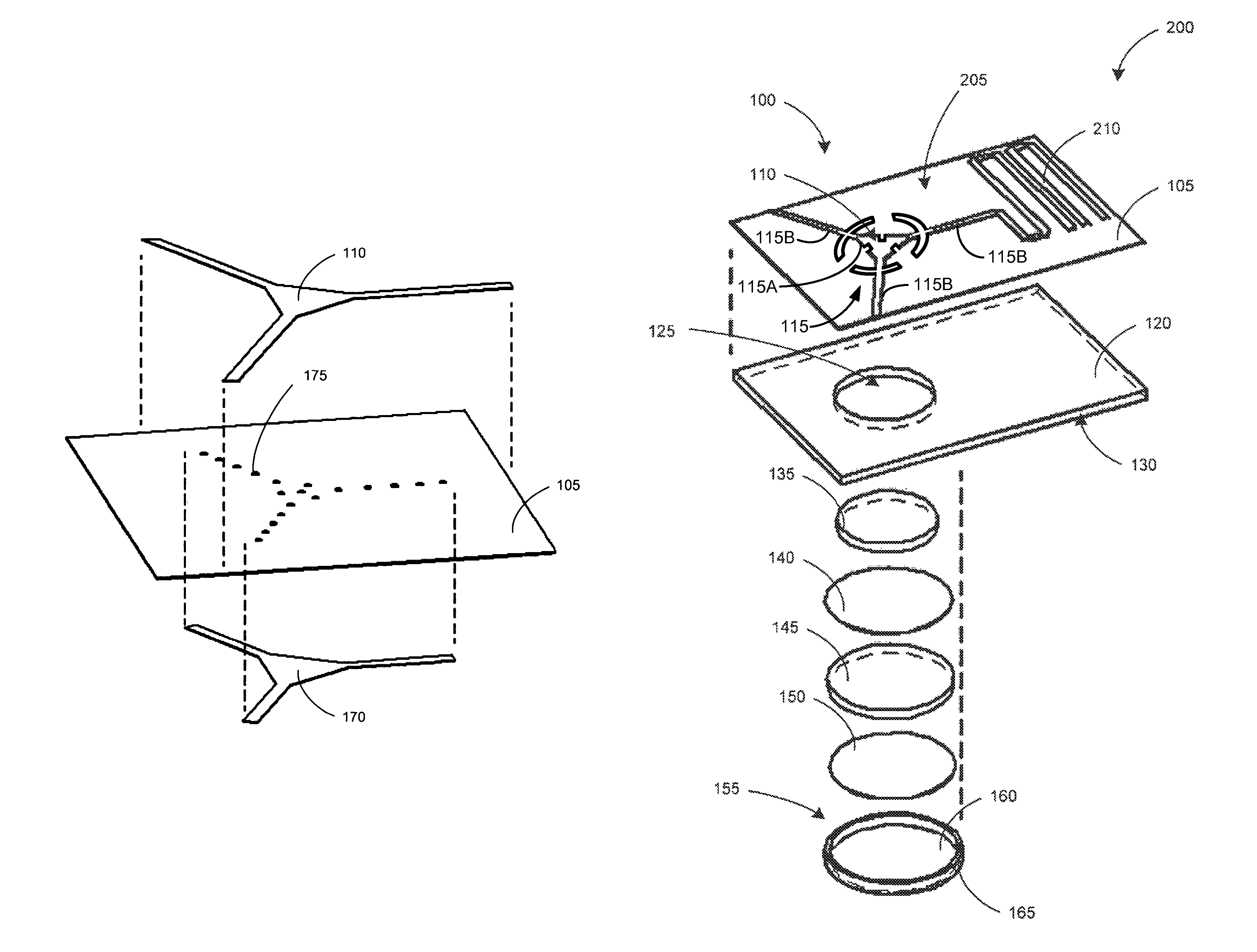
The present invention provides a device, system, and method for creating a continuous circuit trace comprising one or more circulators and one or more external electronic components. This technology eliminates impedance mismatches created between the components, which reduces the need for physical impedance matching using, for example, variable width impedance matching sections between the components and the adjacent circuitry and traces. This technology enables low cost printed circuit board (“PCB”) manufacturing of circulators and overcomes the performance loss normally associated with printed circulators in the PCB environment. The invention can include a first substrate and a continuous circuit trace printed on the first substrate, the continuous circuit trace comprising a first circulator pattern and a first external component. The circulator pattern can comprise a central conductor element and three or more connection ports. The central conductor element can further comprise one or more slots to improve circulator loading. The first external component can comprise a variety of RF electronic components such as a second circulator pattern, a filter, an antenna, a power divider, or a power combiner. To improve circulator performance, the first substrate can be relatively thin.

Problems solved by technology

Although circulators are extremely efficient devices, conventional circulators have several drawbacks.
First, installation of conventional circulators on a circuit board requires that an aperture, which is slightly larger than the circulator package is cut into the circuit board where the circulator is to be installed.
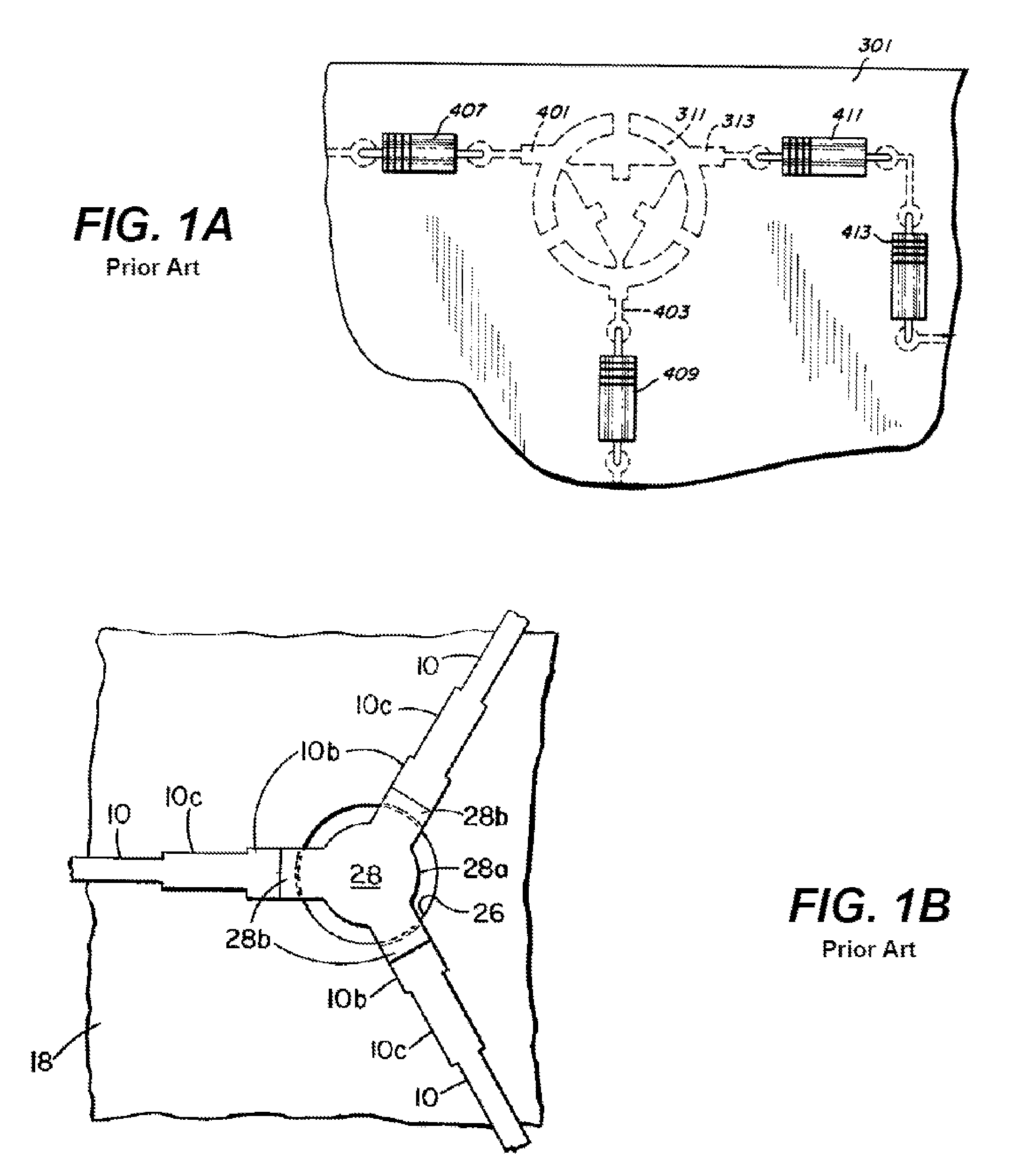
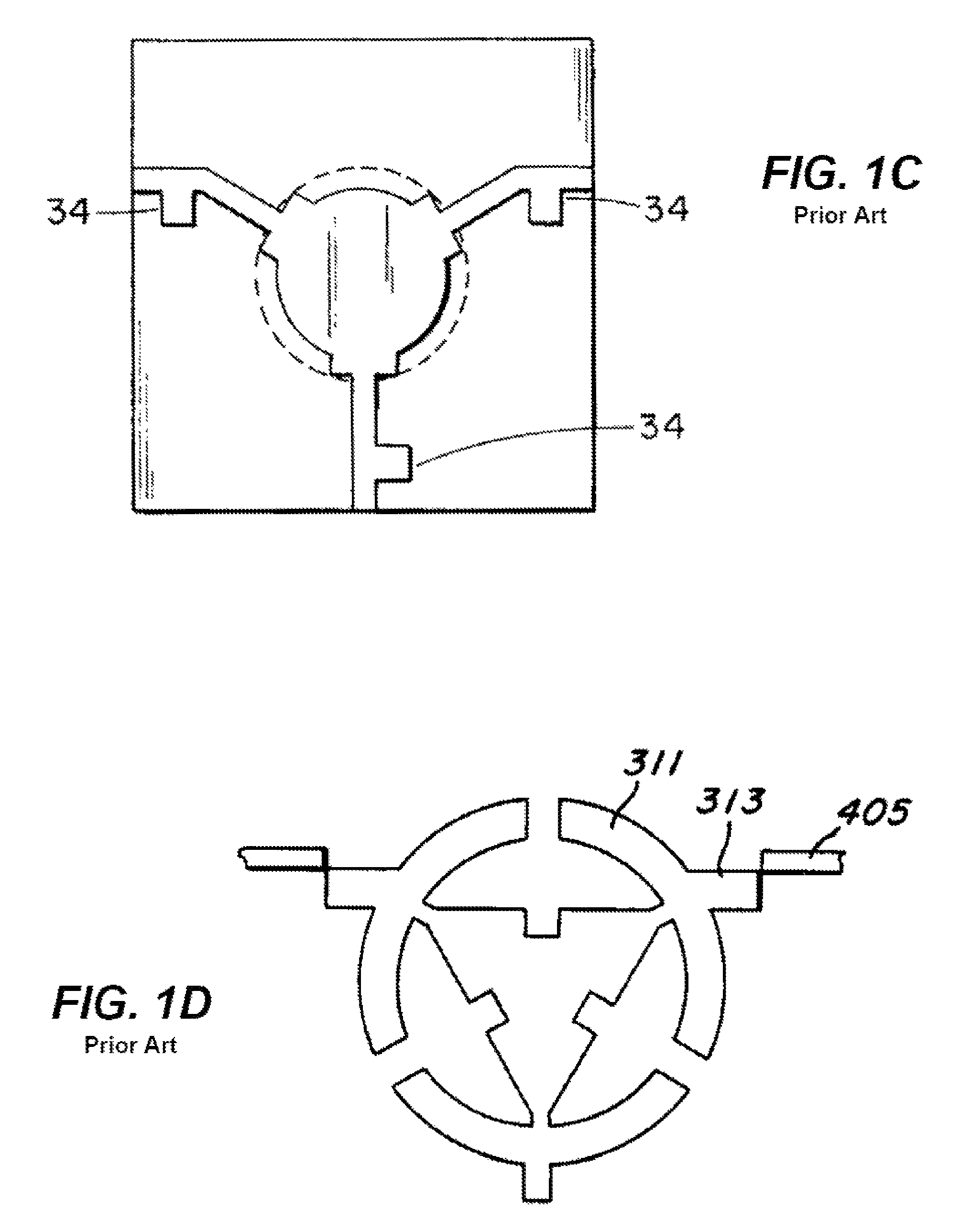
As a result, since the port leads 313, 401, 403 of the circulator are normally made from different materials and have different impendence values from the external components 407, 409, 413, and because these components 407, 409, 413 are soldered to the board, there is an impedance mismatch at the interconnects, which results in a degradation of the electrical performance of the circulator.
This adds complexity to the manufacturing process and requires tuning based on the operational frequency range of the circulator.
Additionally, discontinuities between the circulator and the circuit trace exist at the connection ports.
The manual interconnects also lead to insertion losses at the port connectors, an increase in the interference from unwanted RF signals, and high performance variability of the circulator.
Furthermore, the manual interconnects tend to have poor thermal capabilities, which can lead to a decrease in the amount of signal power that can be passed through the circuit.
Another drawback with conventional circulators is that the circulators do not lie within the same plane as the components of the external circuit.
This makes it difficult to effectively provide a common ground the circulator and the circuit.
This non-planar ground plane can lead to reduction in the electrical performance of the circulator.
Yet another drawback to conventional circulators is that they are expensive to manufacture and cannot be made using an automated manufacturing process.
For example, the ferrite substrates used in conventional circulators tend to be brittle and can be damaged in an automated manufacturing process.
Unfortunately, this assembly process is expensive in both time and money.
Unfortunately this method still must use manual interconnects to connect the cascaded circulators to an exterior circuit.
Furthermore, the circulator elements are disposed between two ferrite substrates, which are easily damaged.
Although the method uses inexpensive materials, this circulator has several drawbacks.
First, the steel disc covers only a portion of the circulator trace, which provides an inadequate ground for the circulator trace and consequently does not adequately shield the circulator trace from spurious RF signals.
Furthermore, since the circulator is designed for surface mounting, the circulator does not lie in-line with the external circuit and therefore, the ground plane of the circuit is non-planar and discontinuous.
The ground plane between the external circuit and the circulator must be bridged with ribbon cables, or other suitable connectors, which results in electrical inefficiencies.
Moreover, since the circulator is surface mounted, it uses manual interconnects to connect the circulator to the external circuit, which result in an impedance mismatch between the circulator and the external circuit.

Method used


Image

  • Integrated circulators sharing a continuous circuit
  • Integrated circulators sharing a continuous circuit
  • Integrated circulators sharing a continuous circuit

Examples


Embodiment Construction

[0044]To facilitate an understanding of the principles and features of the various embodiments of the invention, various illustrative embodiments are explained below. Although preferred embodiments of the invention are explained in detail, it is to be understood that other embodiments are contemplated. Accordingly, it is not intended that the invention is limited in its scope to the details of construction and arrangement of components set forth in the following description or illustrated in the drawings. The invention is capable of other embodiments and of being practiced or carried out in various ways. Also, in describing the preferred embodiments, specific terminology will be resorted to for the sake of clarity.

[0045]It must also be noted that, as used in the specification and the appended claims, the singular forms “a,”“an” and “the” include plural references unless the context clearly dictates otherwise. For example, reference to a component is intended also to include composit...


PUM

PropertyMeasurementUnit
thicknessaaaaaaaaaa
thicknessaaaaaaaaaa
thicknessaaaaaaaaaa

Abstract

The present invention is directed to a circuit assembly that includes an integrated circulator assembly. The circuit assembly has a first substrate, which contains a continuous circuit trace that includes a circulator component from the circulator assembly and at least one electrical component from the circuit assembly. A second substrate is disposed beneath the first substrate and includes a cladding on one surface. The second substrate contains an aperture that accepts a ferrite element, which is axially aligned with the circulator component of the circuit trace. A conductive material is placed across the ferrite element so that it forms a continuous ground plane with the cladding, which is common to the entire circuit trace. The circulator assembly also contains a magnet bonded to the ferrite element. The circulator assembly may also include a yoke disposed below the magnet to shield the circulator from external magnetic fields.

Description

REFERENCE TO RELATED APPLICATIONS[0001]This application is a continuation-in-part of U.S. patent application Ser. No. 11 / 314,160 of the same title filed 19 Dec. 2005, which claims priority to U.S. Provisional Patent Application Ser. No. 60 / 636,945, filed on Dec. 17, 2004. Both Applications are incorporated herein by reference as if fully set forth below.BACKGROUND[0002]1. Field of the Invention[0003]Embodiments of the present invention relate to a device, system, and method for providing continuous circuit traces, and specifically to a device, system, and method for providing continuous circuit traces comprising circulators and other electronic components in a continuous circuit trace, obviating the need for manual interconnects and impedance matching.[0004]2. Description of the Related Art[0005]The use of circulators to isolate and transmit electronic signals is well known. Circulators are multi-port devices, which receive a radio frequency (RF) signals on one port and route them t...

Claims


Application Information

Patent Timeline
Patent Type & Authority Patents(United States)
IPC IPC(8): H01P1/387
CPCH01P1/387H05K3/10H05K1/025Y10T29/49155H05K2201/086
Inventor POPELKA, DAVID J.VAUGHN, TODDVOSS, JOHN D.
Owner EMS TECHNOLOGIES
Learn More