Stabilized shields for magnetic recording heads

a shield and magnetic recording technology, applied in the field of magnetic readwrite heads, can solve the problems of high net moment, difficult stabilization of shield domain state, and high value and range of demagnetizing field

Active Publication Date: 2013-08-20
HEADWAY TECH INC
View PDF21 Cites 14 Cited by
  • Summary
  • Abstract
  • Description
  • Claims
  • Application Information

AI Technical Summary

Benefits of technology

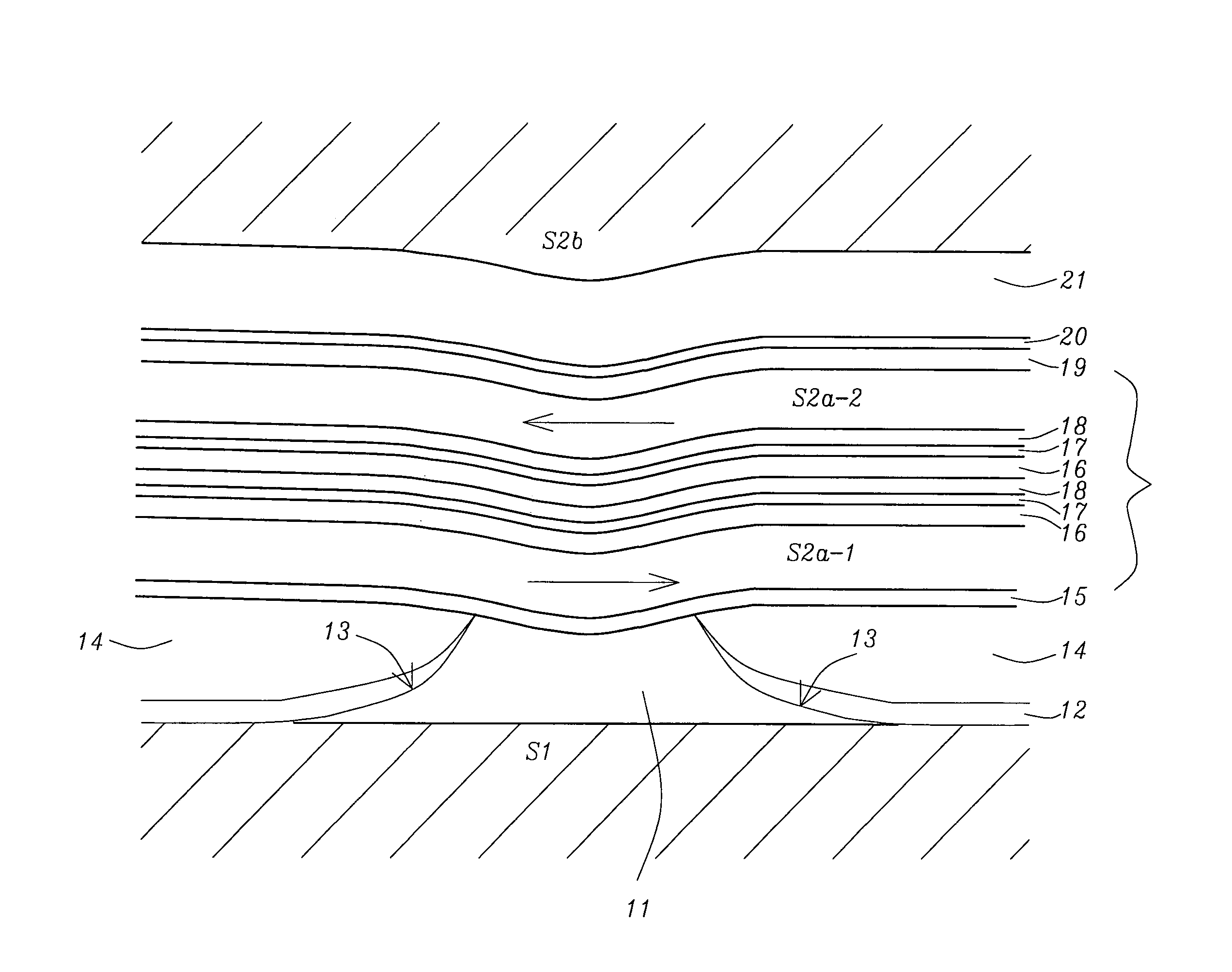
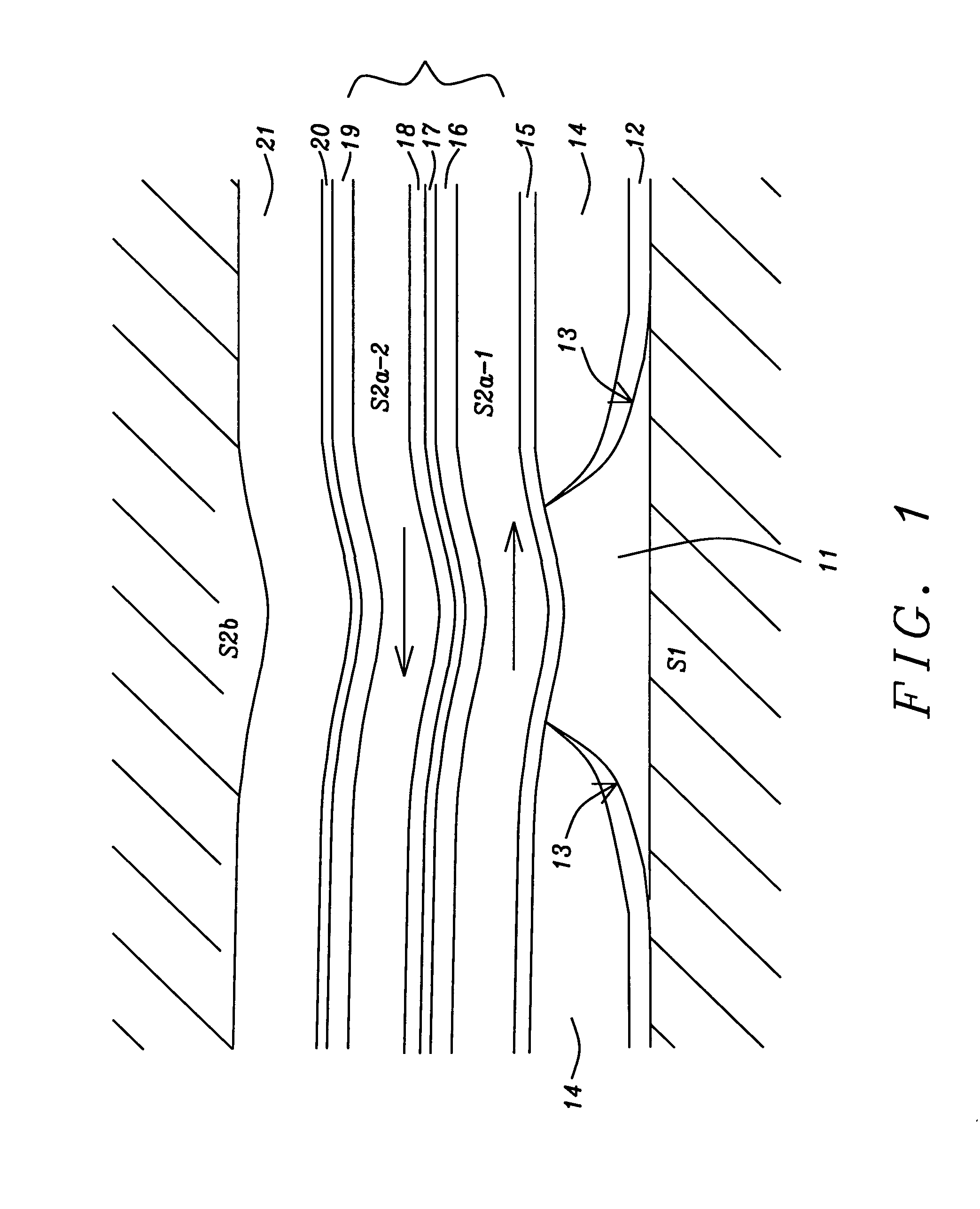
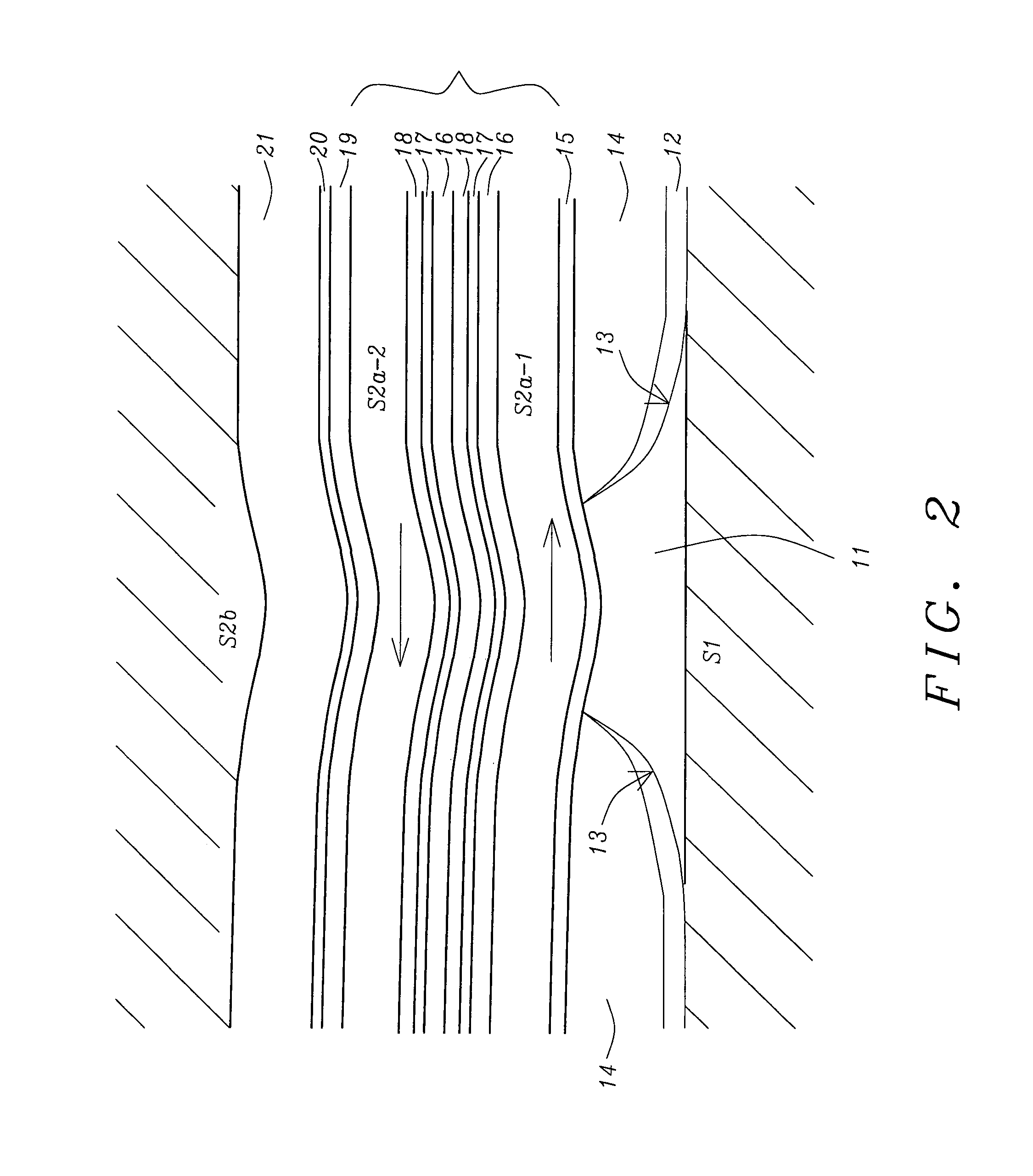
[0010]The use of 2 (or more) antiparallel FM layers allows large reductions (or elimination) of the shield net moment, and consequently allows much better pinning than can be achieved with only a single FM layer. If more the two FM layers are included, the system design is denoted as FM / Ru / FM( . . . / Ru / FM) / AFM, which altogether is referred to as the ‘SAF / AFM’ system. The FM / Ru / FM( . . . / Ru / FM) part is the synthetic antiferromagnet, or SAF. All layers are required in order to achieve stable robust magnetic domain control, with a single preferred magnetic orientation; neighboring FM layers will have opposing or antiparallel domain orientations, by virtue of the AFC coupling.
[0011]Without the AFM layer, the system has multiple stable magnetic domain states. Without the Ru, for example by substituting some other non-AFC spacer, certain of the FM layers would not be stable. With only a single FM layer, the system net moment is high, shield edge demagnetizing field value and range will be very high, and the shield domain state will be difficult to stabilize. The multilayers of the SAF / AFM structure act together as a complete system which is the key part of the new stable shield design disclosed here; the SAF / AFM together with optional supplementary shielding, is called the ‘compound shield.’ This design allows reduction or optimization of read-gap-to-write-gap spacing, simplifies manufacturing, and eliminates some secondary constraints (on junction design) or penalties that burden the current unstable designs.
[0014]Still another object of at least one embodiment of the present invention has been that the SAF / AFM part of the compound shield have a thickness less than 2500 Angstroms, without suffering any performance degradation. For the case of top shield S2, this thinner shield allows reduction of certain write-to-read spacing and other critical head parameters.
[0015]A further object of at least one embodiment of the present invention has been to assure a reproducible shield magnetic domain orientation, a directional anisotropy, and a controlled response or rotation of the shield domains in an applied external field.

Problems solved by technology

With only a single FM layer, the system net moment is high, shield edge demagnetizing field value and range will be very high, and the shield domain state will be difficult to stabilize.

Method used


Image

  • Stabilized shields for magnetic recording heads
  • Stabilized shields for magnetic recording heads
  • Stabilized shields for magnetic recording heads

Examples


Embodiment Construction

[0021]In the description of the invention that follows we will provide details in terms of the top shield (S2) system but it is to be understood that all these features may be applied with comparable effect to improve the bottom shield (S1) system. For the top shield, the preferred embodiments are FM / Ru / FM / AFM or FM / Ru / FM / Ru / FM / AFM (3 FM layer version).

[0022]A thermal anneal at between approx. 150 and 280° C. is preformed at some step after deposition, to set the pinning layer orientation, and establish the intended domain orientation for the FM layers; the anneal can be performed with or without an externally applied field, depending on design optimization considerations.

[0023]The use of 3 FM layers, as opposed to 2 FM layers, results in opposite magnetic domain orientation for the FM layer closest to the sensor (for field anneal in a fixed direction). Because either orientation may be desirable depending on other aspects of the design, both 2 and 3 FM layer designs are among the p...


PUM

PropertyMeasurementUnit
thickaaaaaaaaaa
thickaaaaaaaaaa
total thicknessaaaaaaaaaa

Abstract

A basic design is disclosed for bottom shield (S1) and top shield (S2) of the reader shields in a magnetic read-write head. The critical part of new design includes an antiferromagnetic film which pins an antiferromagnetically coupled trilayer (AFCT). The simplest embodiment for top shield, for example, would be a film sequence of FM / Ru / FM / AFM. This replaces the normal top shield design which typically comprises a ferromagnetic seed layer and a thicker plated ferromagnetic film. Processes for manufacturing these shields are also described.

Description

[0001]This application is related to HT06-041, filed on Aug. 2, 2007 as application Ser. No. 11 / 888,856, and herein incorporated, by reference, in its entirety.FIELD OF THE INVENTION[0002]The invention relates to the general field of magnetic read-write heads with particular reference to stabilizing their associated internal shields.BACKGROUND OF THE INVENTION[0003]Magnetic read-write heads typically include two magnetic shields that are important for the reader part—the shield S1 below the read sensor, also called the bottom shield, and shield S2 immediately above the sensor, also called the top shield. Current typical thick film shield designs have several problems, including magnetic stability problems, increased spacing between reader and writer, and manufacturing and other issues. Changes in shield magnetic domain states can cause sensor signal changes; these are the so-called shield magnetic stability problems which may arise from applied external fields, media fields, interna...

Claims


Application Information

Patent Timeline
Patent Type & Authority Patents(United States)
IPC IPC(8): G11B5/33G11B5/127
CPCG11B5/3163G11B5/398G11B5/3912
Inventor WU, YANGARFUNKEL, GLENLI, MINIWAI, YUZURUDOVEK, MORIS
Owner HEADWAY TECH INC
Why Eureka
Try Eureka