
Chain-link converter, method for starting chain-link converter and static compensator system

a converter and chain-link technology, applied in the direction of dc-ac conversion without reversal, process and machine control, instruments, etc., can solve the problems of reducing the service life of the converter, the risk of diodes being damaged during the start-up of the converter, and the solution is not cheap enough, so as to reduce the stress on the included diodes and eliminate the effect of related damag

Active Publication Date: 2013-08-20
ABB POWER GRIDS SWITZERLAND AG
View PDF5 Cites 2 Cited by
  • Summary
  • Abstract
  • Description
  • Claims
  • Application Information

AI Technical Summary

Benefits of technology

[0013]It is another object of the invention to provide a chain-link converter wherein the stress put on the included diodes is minimized and related damages eliminated.
[0014]It is yet another object of the invention to provide a chain-link converter having a cost-efficient design, eliminating the prior art starting resistors and switches.
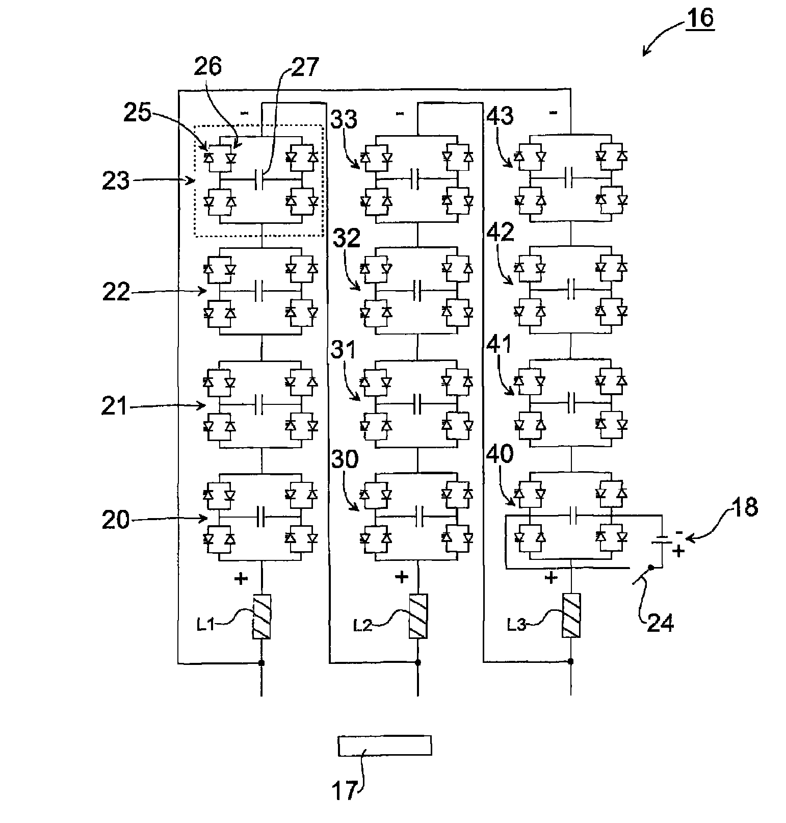
[0016]In accordance with the invention a chain-link converter is provided comprising one or more phases. The one or more phases each comprise one or more series-connected converter cells. The chain-link converter is characterised by a power source that is connected to a converter cell of one of the one or more phases. By means of the invention, the diodes of the chain-link converter cells experience no stress and a reliable converter is provided. Further, by means of the innovative start-up arrangement of the chain-link converter, the starting resistors and switches can be omitted, thus providing a more cost-efficient solution. Further yet, the chain-link converter can easily be adapted to a wide range of power network voltages by using a suitable number of cells.

Problems solved by technology

This in turn entails the risk of the diodes being damaged during the start-up of the converter.
Although the starting resistors and switches provide a functioning solution, it is a rather expensive solution and it would be desirable to lower the costs of the converter.
It is conceivable to use diodes able to handle larger currents, but this is still an expensive solution.

Method used


Image

  • Chain-link converter, method for starting chain-link converter and static compensator system
  • Chain-link converter, method for starting chain-link converter and static compensator system
  • Chain-link converter, method for starting chain-link converter and static compensator system

Examples


Embodiment Construction

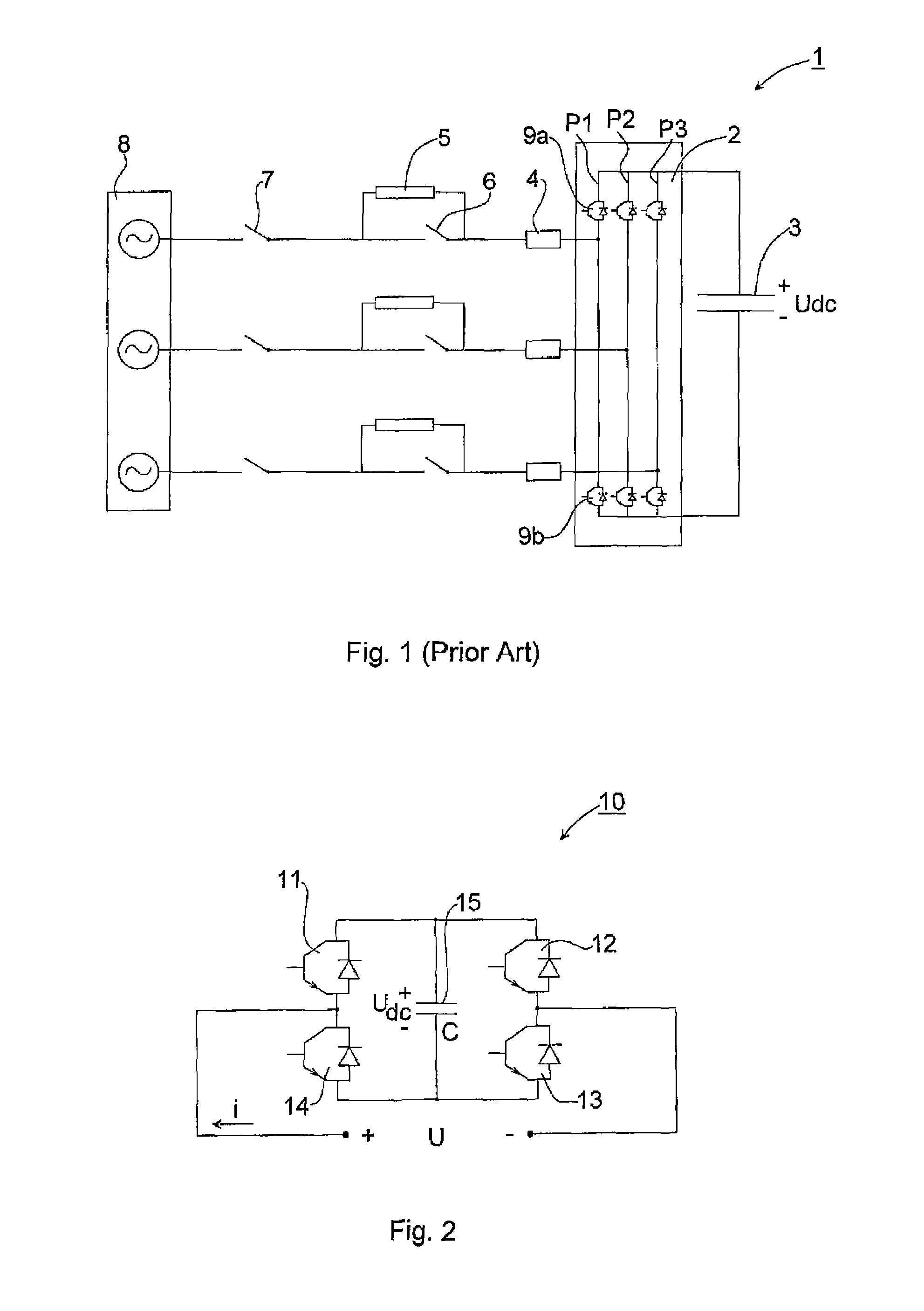
[0025]FIG. 1 has already been described in the introductory part of the application and will not be described further.

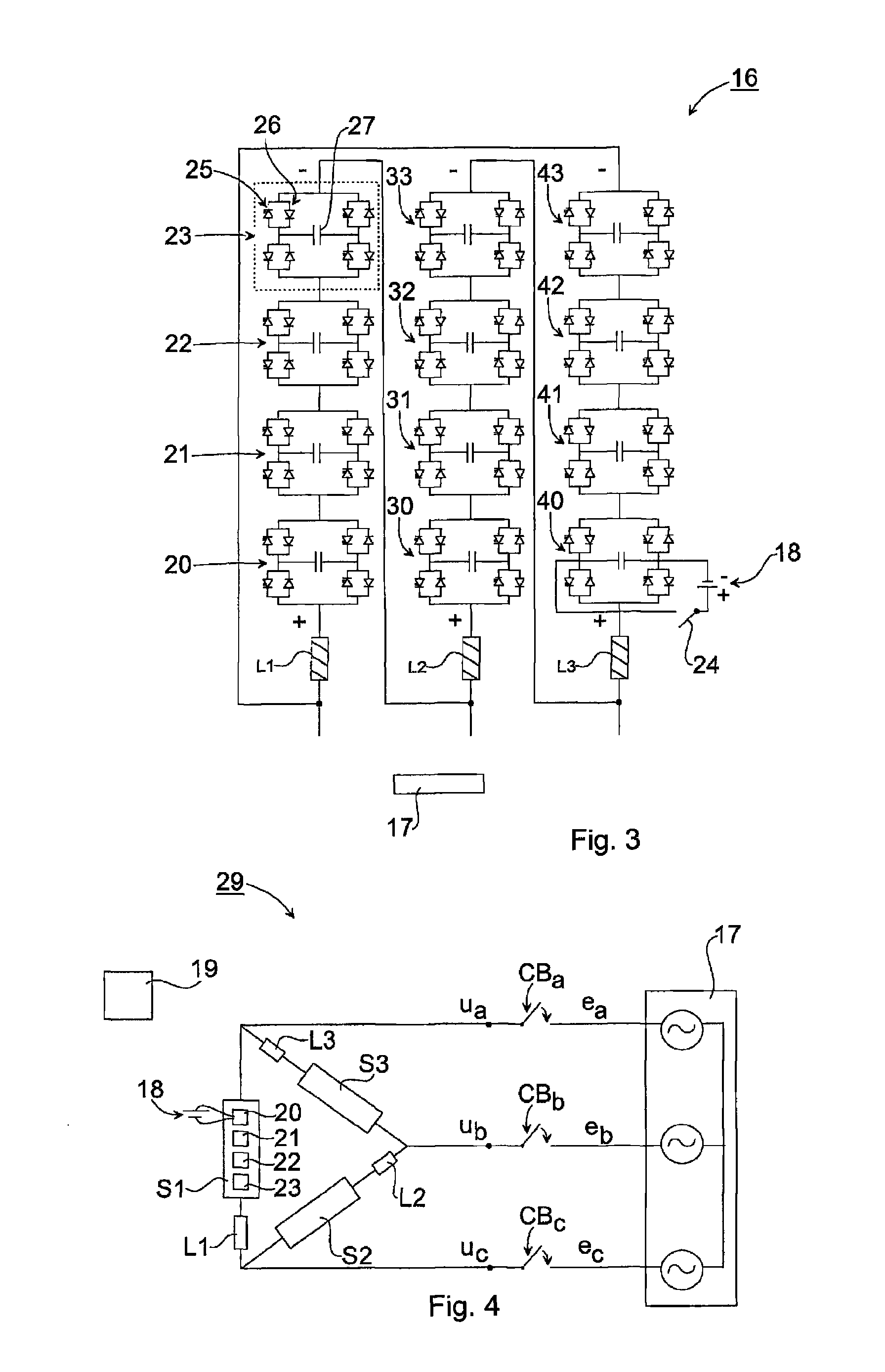
[0026]Same reference numerals are used throughout the FIGS. 2-4 for denoting same or corresponding parts.

[0027]FIG. 2 illustrates one converter link, also denoted converter cell, of a chain-link converter in accordance with the present invention. The converter cell 10 comprises four valves 11, 12, 13, 14, each valve including a transistor switch, such as an insulated gate bipolar transistor (IGBT). In the following an IGBT is used as an example, but it is noted that other semiconductor devices could be used, for example gate turn-off thyristors (GTO) or Integrated Gate Commutated Thyristors (IGCT). A free-wheeling diode, also denoted anti-parallel diode, is connected in parallel with each IGBT. The diode conducts in the opposite direction of the IGBT. The valves 11, 12, 13, 14 are connected in an H-bridge arrangement with a capacitor unit 15.

[0028]FIG. 3 illustrates ...


PUM


Abstract

A chain-link converter including one or more phases. The one or more phases each includes one or more series-connected converter cells. The chain-link converter includes a power source connected to a converter cell of one of the one or more phases. A cost-efficient start-up of the converter is provided. The invention also relates to a corresponding static compensator system and a method.

Description

CROSS-REFERENCE TO RELATED APPLICATIONS[0001]The present application is a continuation of pending International patent application PCT / EP2008 / 065160 filed on Nov. 7, 2008 which designates the United States, the content of which is incorporated herein by reference.FIELD OF THE INVENTION[0002]The invention relates to the field of power compensation in a high-voltage power network, and in particular to static compensators based on chain-link converters.BACKGROUND OF THE INVENTION[0003]Static Var Compensator (SVC) systems have been used in power networks for many years for controlling generation and absorption of reactive power in a power network in order to provide voltage support, improve transient stability and to damp oscillations. A STATCOM (STATic COMpensator) is a kind of a SVC, being a Voltage Source Converter (VSC) based device that can act as either a source or sink of reactive AC power to the power network. The STATCOM can also provide active power if it is connected to a DC ...

Claims


Application Information

Patent Timeline
Patent Type & Authority Patents(United States)
IPC IPC(8): H02M1/36
CPCH02J3/1857H02J3/1864H02M1/36H02M7/49Y02E40/12Y02E40/26H02M2007/4835H02M7/4835Y02E40/10Y02E40/20
Inventor SVENSSON, JAN R.
Owner ABB POWER GRIDS SWITZERLAND AG
Learn More