Turbine cooling air sealing

a technology for cooling air sealing and turbines, applied in waterborne vessels, machines/engines, blade accessories, etc., can solve the problems of reducing the overall turbine efficiency, reducing engine efficiency, and particularly challenging inner cavity areas

Active Publication Date: 2013-08-27
RTX CORP +1
View PDF28 Cites 29 Cited by
  • Summary
  • Abstract
  • Description
  • Claims
  • Application Information

AI Technical Summary

Benefits of technology

[0008]One aspect of the invention involves a turbine engine section having a stationary vane stage and a rotating blade stage. The blade stage is spaced from the vane stage to form an annular chamber therebetween. A manifold delivers a pressurized fluid to the chamber. An outer diameter (OD) sealing means restricts leakage of the pressurized fluid from the chamber. An inner diameter (ID) sealing means restricts leakage of the pressurized fluid from the chamber. A baffle or flow guide extends radially between the inner diameter sealing means and the manifold. The flow guide bisects the chamber to form a stationary chamber portion and a rotating chamber portion, the rotating chamber portion at least partially along a disk of the first blade stage.

Problems solved by technology

This area of the inner cavity is particularly challenging to seal, due to the differences in thermal and centrifugal growth between the stationary first-stage vane frame and the rotating first stage rotor assembly.
This pumping action increases the temperature of the disk in the area of the blades and creates parasitic drag, which reduces overall turbine efficiency.
The rotating knife-edges also add additional rotational mass to the gas turbine engine, which further reduces engine efficiency.
The seal's bristle-to-land contact pressure increases during the maximum radial excursions of the rotor and may cause the bristles to deflect and set over time, reducing the leakage restriction capability during low to intermediate rotor excursions.
This pumping action increases the temperature of the disk in the area of the blades and creates parasitic drag, which reduces overall turbine efficiency.
The freestanding sideplate and minidisk also adds rotational mass to the gas turbine engine, which further reduces engine efficiency.

Method used


Image

  • Turbine cooling air sealing
  • Turbine cooling air sealing
  • Turbine cooling air sealing

Examples


Embodiment Construction

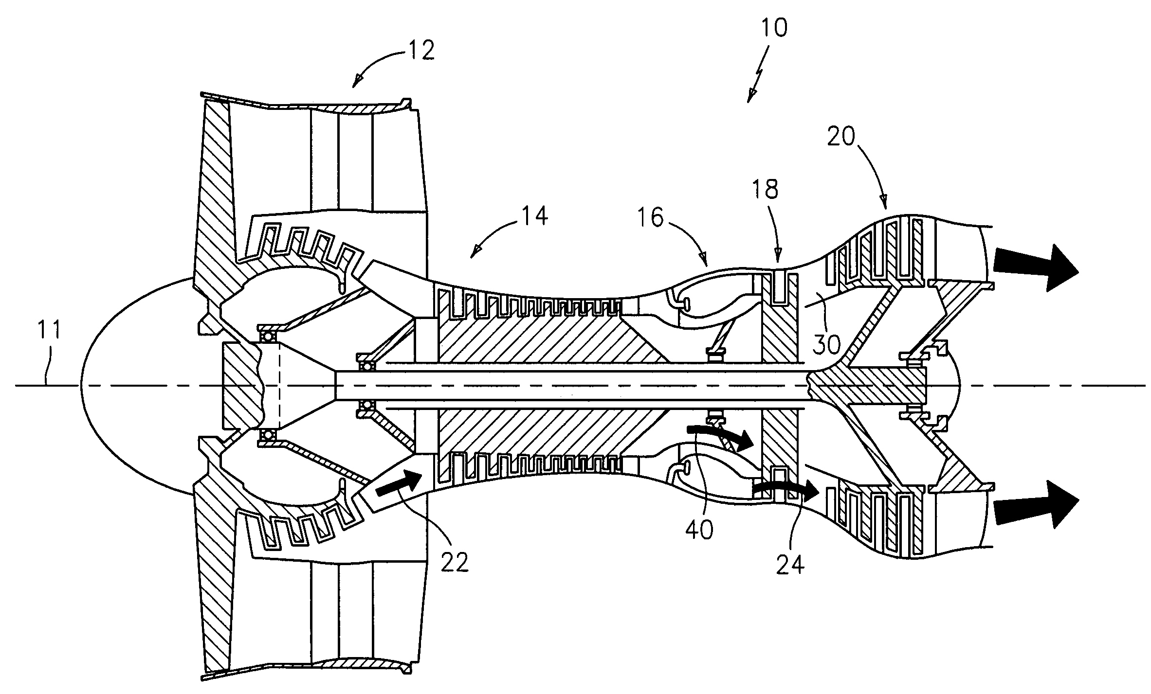
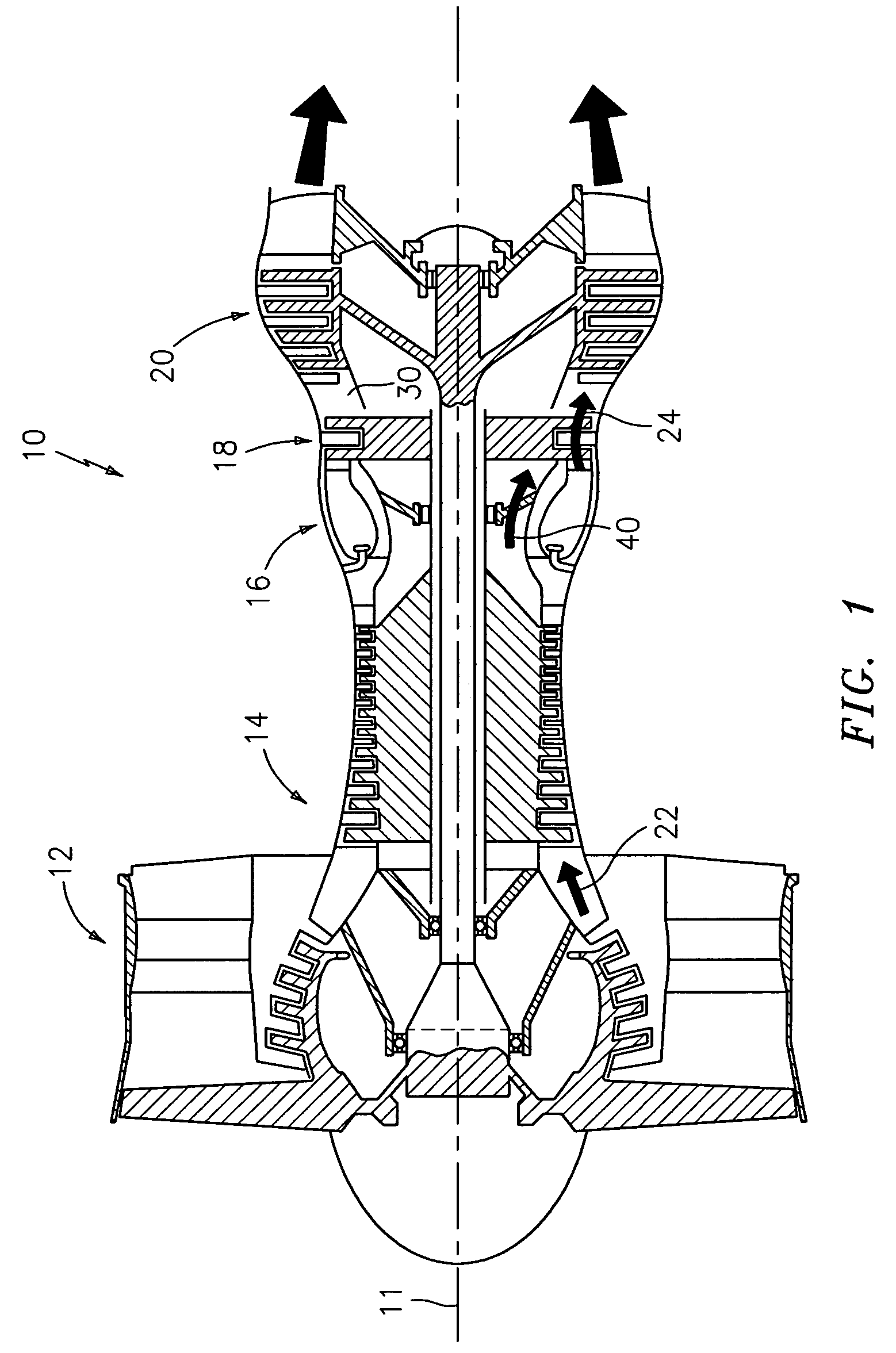
[0027]The major sections of a typical gas turbine engine 10 of FIG. 1 include in series, from front to rear and disposed about a central longitudinal axis 11, a low-pressure compressor 12, a high-pressure compressor 14, a combustor 16, a high-pressure turbine module 18 and a low-pressure turbine module 20. A working fluid 22 is directed generally downstream / rearward through the compressors 12, 14 and into the combustor 16, where fuel is injected and the mixture is burned. Hot combustion gases 24 exit the combustor 16 and expand within a core flowpath in an annular duct 30 through the turbines 18, 20 and exit the engine 10 as a propulsive thrust. A portion of the working fluid 22 exiting the high-pressure compressor 14, bypasses the combustor 16 and is directed to the high-pressure turbine module 18 for use as cooling air 40.

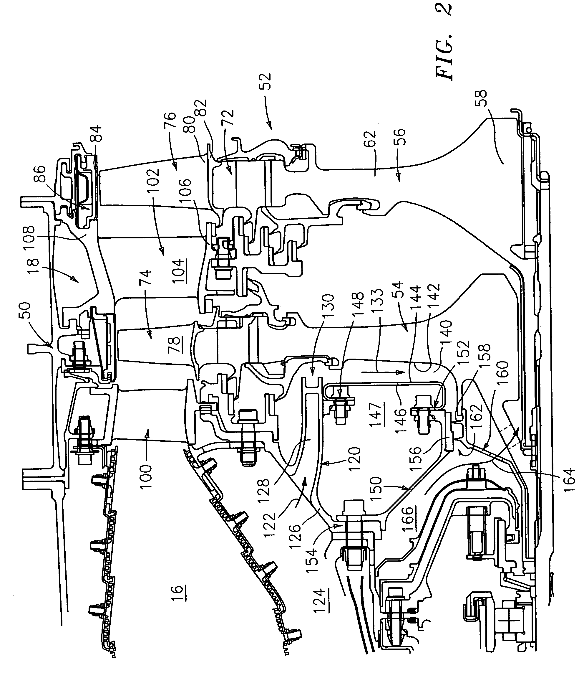
[0028]FIG. 2 shows further details of the interface between the downstream end of the combustor 16 and the upstream end of the high pressure turbine module 18. W...


PUM


Abstract

A turbine engine section has a stationary vane stage and a rotating blade stage. The blade stage is spaced from the vane stage to form an annular chamber therebetween. A manifold delivers a pressurized fluid to the chamber. An outer diameter (OD) sealing system restricts leakage of the pressurized fluid from the chamber. An inner diameter (ID) sealing system restricts leakage of the pressurized fluid from the chamber. A flow guide extends radially between the inner diameter sealing system and the manifold. The flow guide bisects the chamber to form a stationary chamber portion and a rotating chamber portion, the rotating chamber portion at least partially along a disk of the first blade stage.

Description

BACKGROUND OF THE INVENTION[0001]The invention relates to gas turbine engines, and more specifically to a seal system for providing a fluid leakage restriction between components within such engines.[0002]Gas turbine engines operate by burning a combustible fuel-air mixture in a combustor and converting the energy of combustion into a propulsive force. Combustion gases are directed axially rearward from the combustor through an annular duct, interacting with a plurality of turbine blade stages disposed within the duct. The blades transfer the combustion gas energy to one or more disks, rotationally disposed about a central, longitudinal axis of the engine. In a typical turbine section, there are multiple, alternating stages of stationary vanes and rotating blades disposed in the annular duct.[0003]Because the combustion gas temperature may reach 2000° F. or more, some blade and vane stages are cooled with lower temperature cooling air for improved durability. Air for cooling the fir...

Claims


Application Information

Patent Timeline
Patent Type & Authority Patents(United States)
IPC IPC(8): F01D5/08F01D5/18
CPCF01D5/081F01D11/001F01D25/12F02C7/18F02C7/28
Inventor ALVANOS, IOANNISAGRAWAL, RAJENDRA K.PINERO, HECTOR M.
Owner RTX CORP
Why Eureka
Try Eureka