Method of measuring a distance between two radio-communication devices and device adapted to implement one such method

a radiocommunication device and distance measurement technology, applied in the direction of measurement devices, transmission monitoring, instruments, etc., can solve the problems of inconvenient operation, inconvenient measurement and/or control, and inability to accurately estimate the distance between two radiocommunication devices, and achieve the effect of reducing energy consumption, reducing the accuracy of the duly obtained distance estimation, and improving the accuracy of the obtained distance estimation

Active Publication Date: 2013-08-27
ORANGE SA (FR)
View PDF16 Cites 9 Cited by
  • Summary
  • Abstract
  • Description
  • Claims
  • Application Information

AI Technical Summary

Benefits of technology

[0019]One aim of the present invention is therefore to propose a method of measuring the di...

Problems solved by technology

Such methods consequently require storage, measurement and/or control means that are complex.
However, when the two devices are fairly close together, the accuracy of a duly obtained distance estimation is strongly affected by an uncertainty relating to the intermediate delay between the reception of the request by the second device and the transmission of the acknowledgement signal by said device.
Consequently, the distance measuring method based on an exchange of channel measurement frames as described above presents the following drawbacks:two channel measurement frames are transmitted in total, which corresponds to a large quantity of energy consumed in the radiocommunication devices.
Such energy consumption is disadvantageous in the case of mobile devices with autonomous energy supply;each channel measurement frame requires a significant time to construct and transmit said frame.
If the device for which such a frame is intended is not available, the energy consumed in the transmitting device and the radio resource used to transmit the frame are lost;th...

Method used


Image

  • Method of measuring a distance between two radio-communication devices and device adapted to implement one such method
  • Method of measuring a distance between two radio-communication devices and device adapted to implement one such method
  • Method of measuring a distance between two radio-communication devices and device adapted to implement one such method

Examples


Embodiment Construction

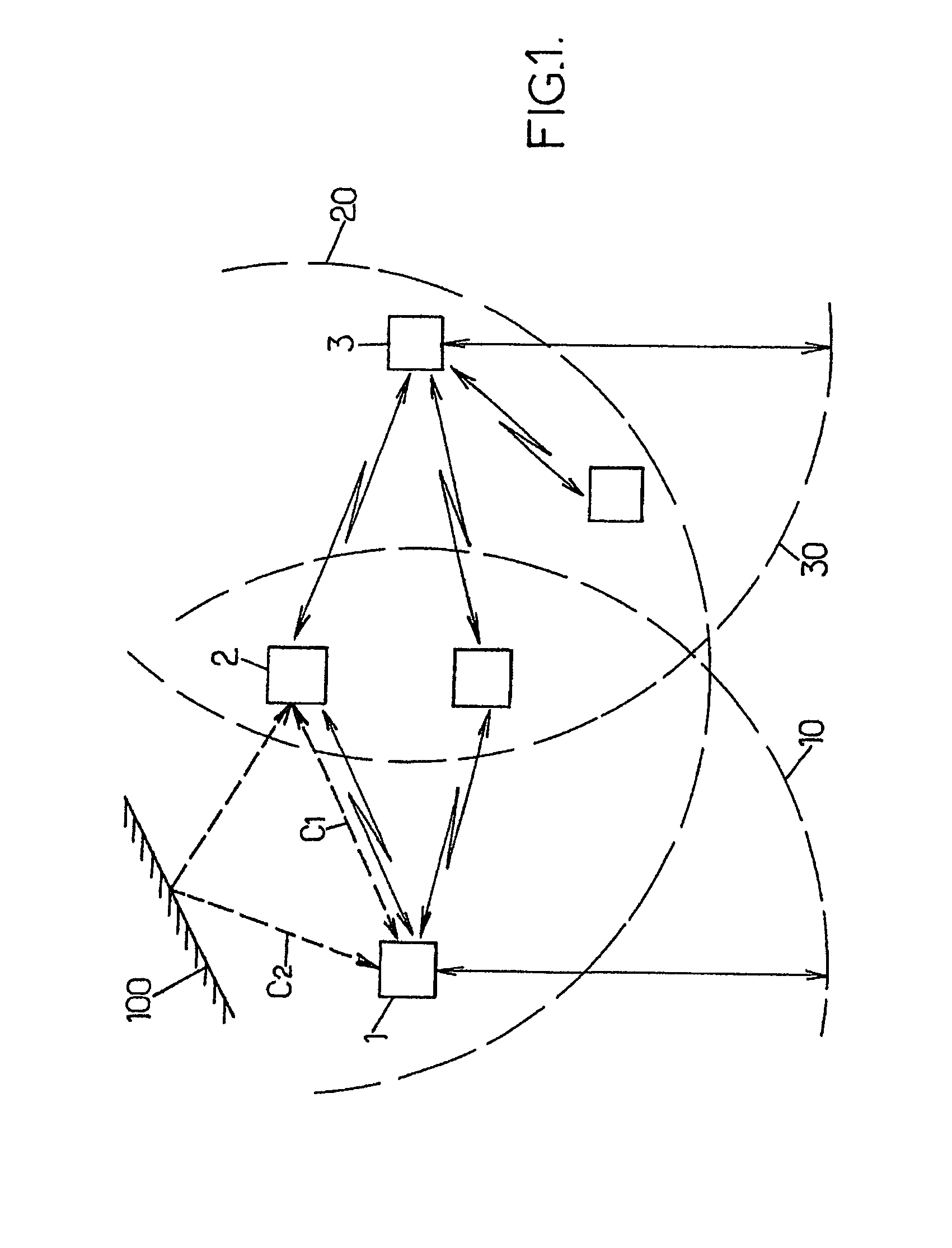
[0042]According to FIG. 1, a communication system comprises a set of radio transmitter-receiver devices, three of which are referenced 1, 2 and 3. Each transmitter-receiver can constitute the radio interface of a sensor forming part of a home automation management system, for example. For such an application, certain sensors can be dedicated to thermal measurements, others to identifying the state of heating element control units, and so on. It can be an “ad hoc” system, which in turn manages the communication sequences between the various sensors. This can be, in particular, a Bluetooth®-type (i.e., wireless-type) system known to those skilled in the art. The broken-line curves 10, 20 and 30 in the figure diagrammatically indicate the respective range limits of the devices 1, 2 and 3. Thus, the device 2 can communicate with each of the devices 1 and 3, whereas the latter are out of radio range of each other.

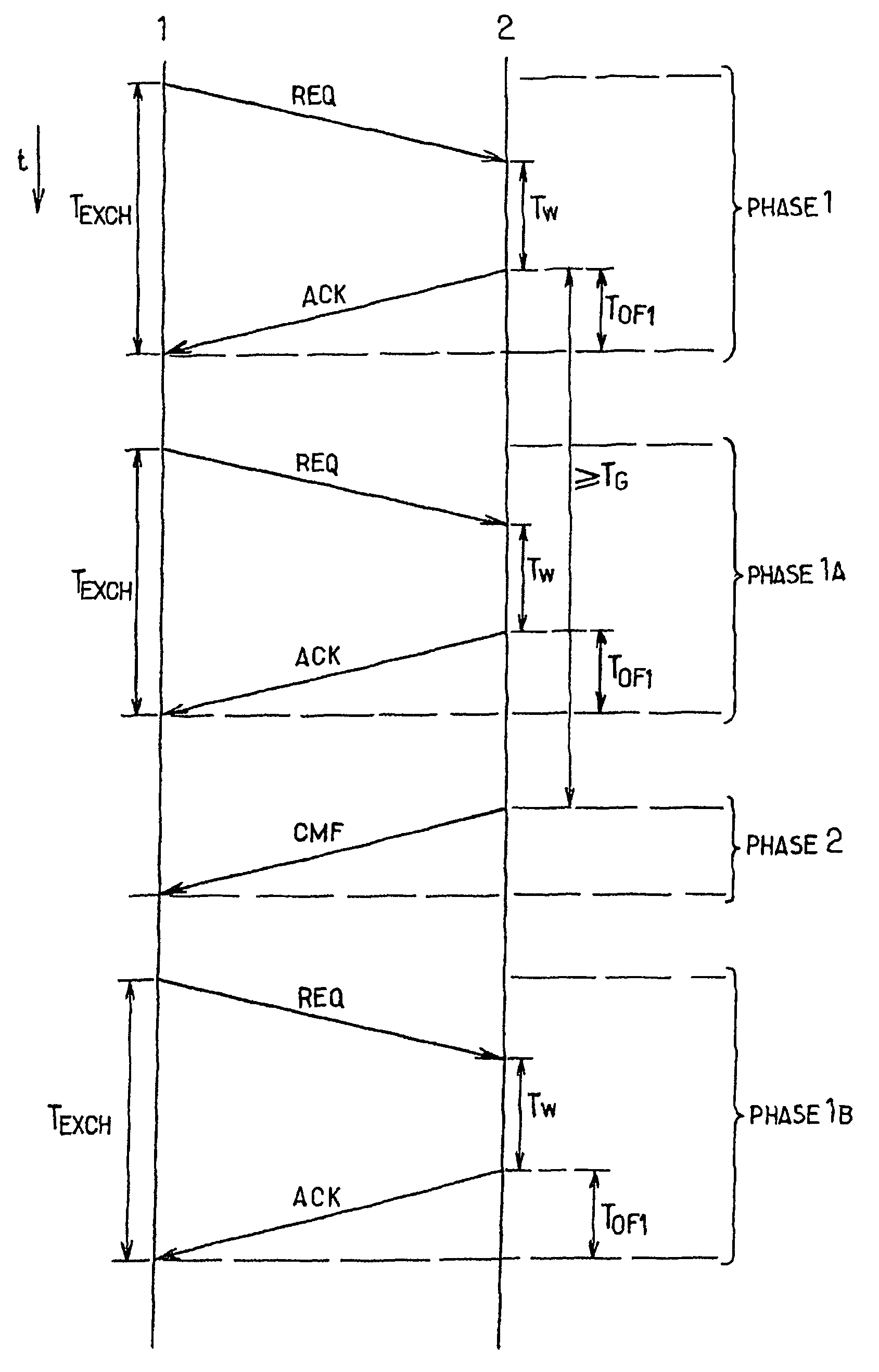
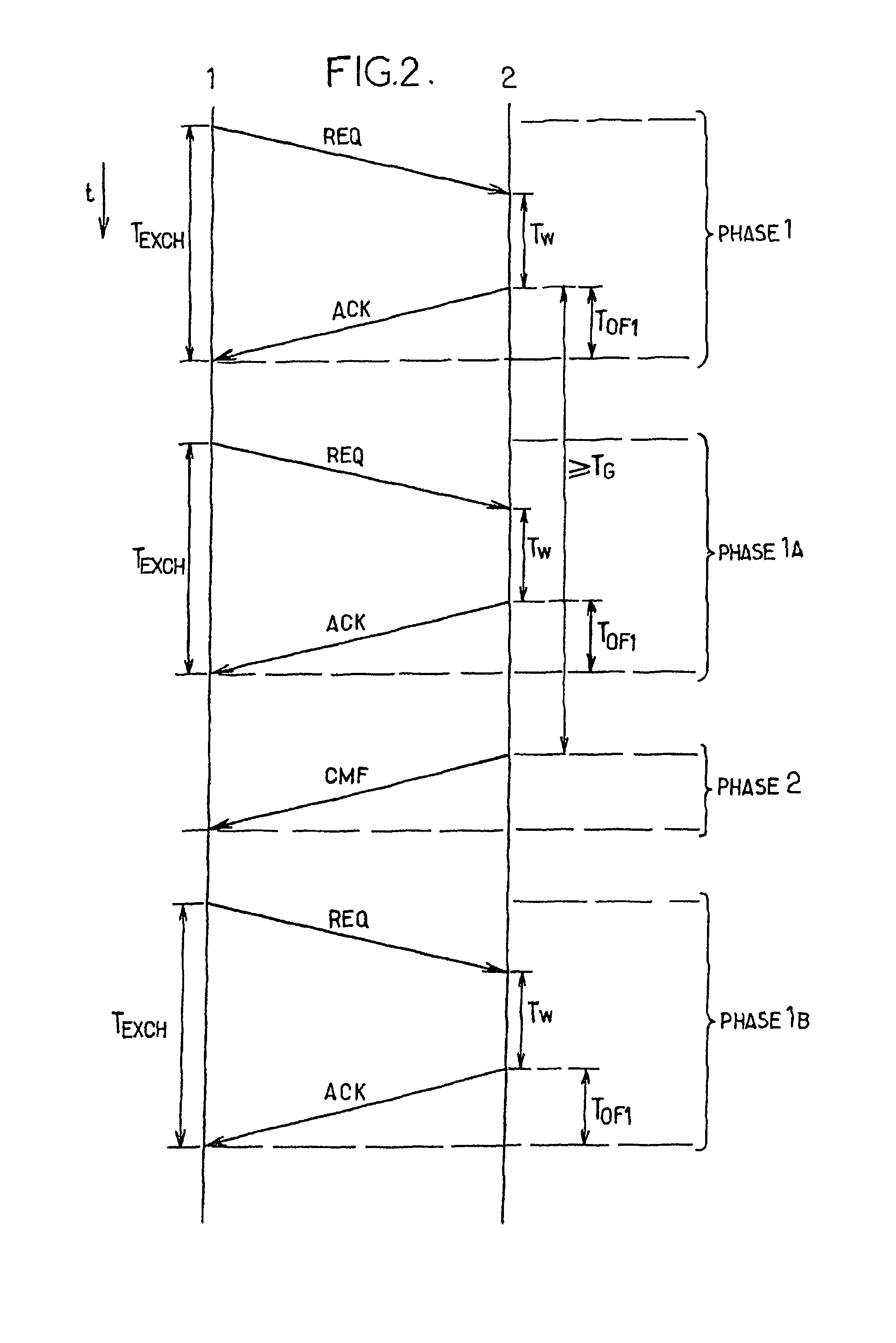
[0043]FIG. 2 indicates the various actions carried out in the devices 1 and...


PUM


Abstract

The invention relates to a method of measuring a distance between two radio-communication devices (1, 2), consisting in measuring a radio signal exchange delay. According to the invention, the time-of-flight of the signals is calculated from the exchange delay and subsequently corrected using an analysis of a single channel measuring frame that is transmitted between the two devices. The corrected time-of-flight corresponds to the shortest propagation path followed by the radio signals. In the majority of radio transmission medium configurations, the corrected time-of-flight is a straight line measurement of the distance separating the two devices (1, 2).

Description

[0001]This application claims priority from PCT / FR2005 / 003275 filed Dec. 23, 2005, which claims the priority from French Application FR 05 00015, filed Jan. 03, 2005, both of which are hereby incorporated by reference in their entirety.BACKGROUND OF THE INVENTION[0002]The present invention relates to a method of measuring a distance between radiocommunication devices, and a device suitable for implementing such a method.[0003]It is often useful to know the position of a radiocommunication device. Such is the case, in particular, when contextual information, that is, the relevance of which depends on the position of the user of the equipment, needs to be transmitted. Such is also the case when a mobile radiocommunication device is linked to a meshed network or to an “ad hoc” network which uses a routing algorithm based on the position of the mobile device. The term “ad hoc” network is used to mean a transmission network capable of recognizing changes to the latter autonomously, that ...

Claims


Application Information

Patent Timeline
IPC IPC(8): H04B17/00H04W64/00
CPCH04W64/00
Inventor MISCOPEIN, BENOITSCHWOERER, JEANEVENNOU, FREDERIC
Owner ORANGE SA (FR)
Why Eureka
Try Eureka