Axial face seal assembly, mounting method and mounting fixture

a technology of axial face seal and mounting method, which is applied in the direction of engine seals, non-positive displacement fluid engines, pump components, etc., can solve the problems of inconvenient removal of structure from housing, limited space available about drive shaft, etc., and achieve the effect of simplifying the handling of seal assemblies

Active Publication Date: 2013-09-03
XYLEM IP HLDG
View PDF9 Cites 12 Cited by
  • Summary
  • Abstract
  • Description
  • Claims
  • Application Information

AI Technical Summary

Benefits of technology

[0012]Another object of the present invention is to provide an axial face seal assembly which is securable axially and non-rotatably to a drive shaft in a rotary machine, and which is structured to avoid machining of the drive shaft in order to locate the seal assembly on the drive shaft.
[0013]Yet another object of the present invention is to provide an axial face seal assembly adapted for a mounting procedure by which a proper axial bias of a seal member can be ensured on a continuous drive shaft surface.
[0014]Still another object of the present invention is to provide an axial face seal assembly adapted for a mounting procedure by which a proper axial bias of a seal member can be ensured on a continuous drive shaft surface by means of a mounting fixture.
[0019]This embodiment secures the option of arranging the seal assembly for mounting / dismounting in procedures that require only axial access to the seal assembly.
[0025]It is preferred that the carrier is non-rotatably connectable to the base member by means of at least one dowel projecting from the bottom end of the carrier and insertable into a corresponding dowel-hole mouthing in both ends of the base member. This embodiment facilitates interaction with a mounting fixture used in a mounting procedure which ensures that a proper axial compression of the spring member, which is interposed between the base member and the carrier, can always be set upon mounting.

Problems solved by technology

In many rotary machines the space available about the drive shaft is however limited, and replacement of the seal assembly requires in most designs that the machine housing is opened.
Albeit Aparicio's solution meets the object of a mounting procedure requiring axial access only, the structure inconveniently falls out of the housing if the impeller was to be dismounted for replacement.

Method used


Image

  • Axial face seal assembly, mounting method and mounting fixture
  • Axial face seal assembly, mounting method and mounting fixture
  • Axial face seal assembly, mounting method and mounting fixture

Examples


Embodiment Construction

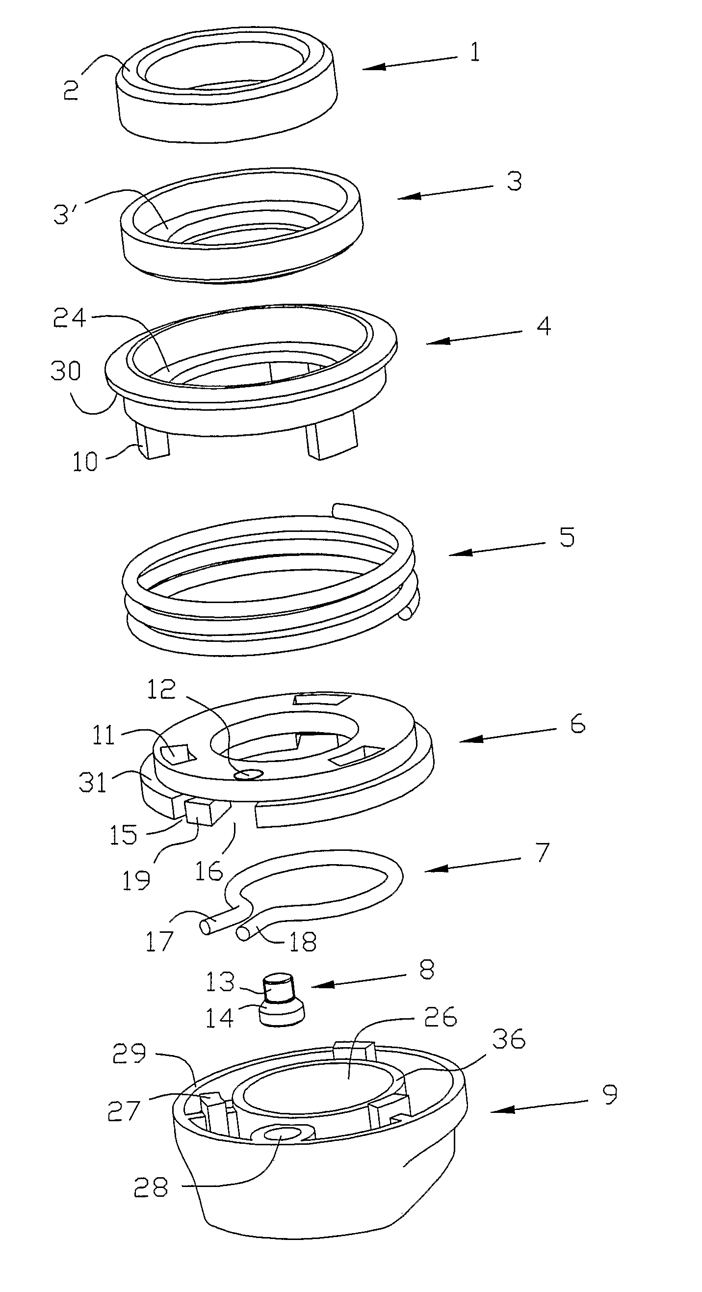
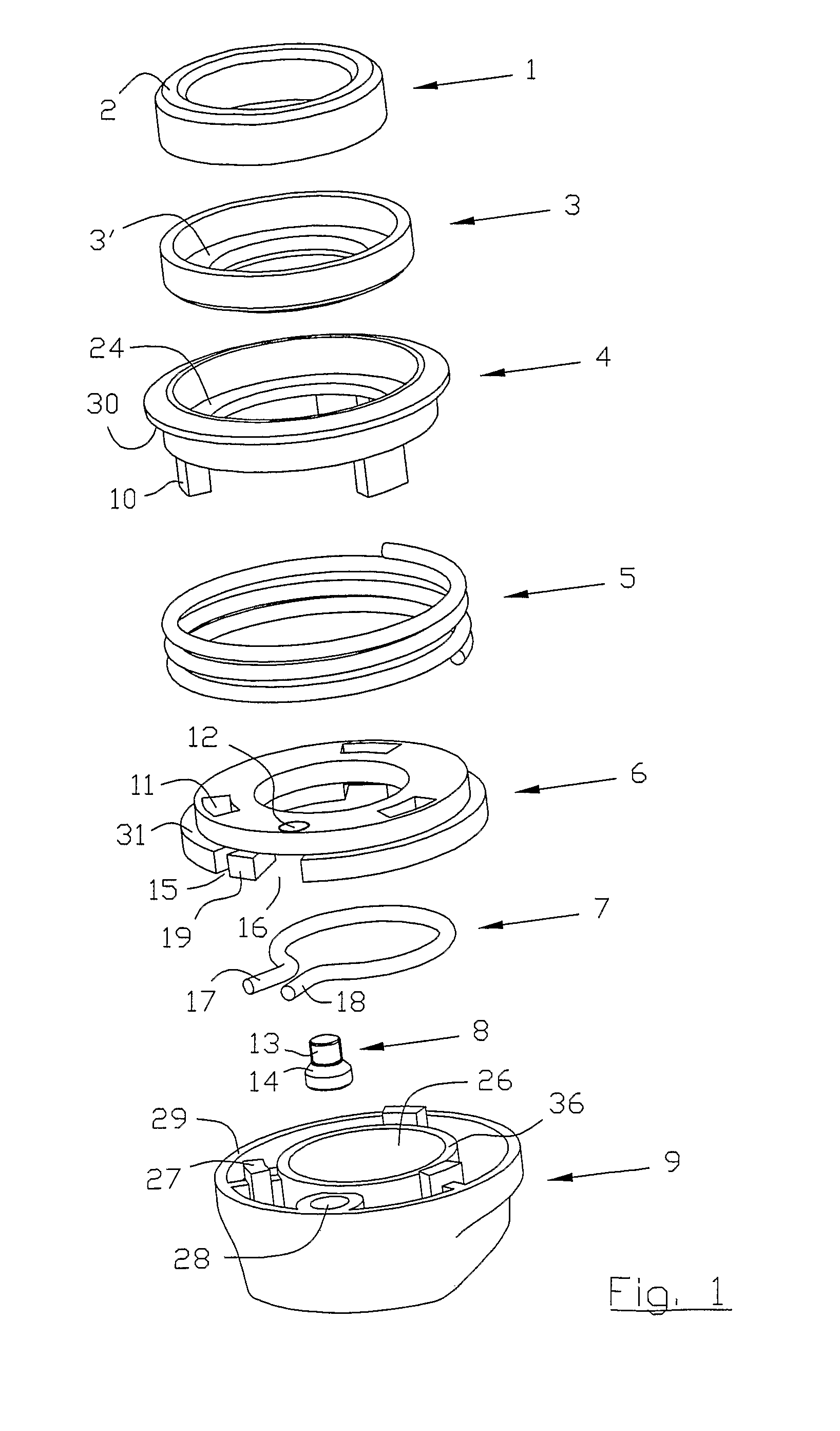
[0039]The essential components comprised in the axial face seal assembly are illustrated in exploded view in FIG. 1. The components are shown in consecutive order from top to bottom of the drawing, the illustrated relative positions of components explaining any reference made herein to top and bottom ends of the components.

[0040]From the top of the drawing, the seal assembly comprises an annular seal member 1 presenting a sealing end face 2 in its top end. Reference numeral 3 indicates an annular seal element made of elastomer material, the elastomer seal 3 adapted to be interposed between the seal member 1 and a carrier 4. A compression spring 5 is interposed between an annular base member 6 and the carrier 4, the compression spring exerting an axial force that applies a bias to the carrier and seal members in the axial direction. The base member 6 is axially and non-rotatably securable to the drive shaft by means of an open ring clamp 7, which is arranged to be housed in the inner...


PUM


Abstract

An axial face seal assembly including a seal member which is seated in a carrier, the carrier being non-rotatably connected to a base member but movable axially thereto and biased from the base member by means of a compression spring interposed between the base member and the carrier, the base member being axially and non-rotatably securable to a drive shaft by means of an open ring clamp having first end second ends. The ring clamp is supported on the base member, at least one of said first and second ends being movable relative to the other end in a circumferential direction; and wherein tightening means is rotatably journalled on the base member for adjusting the relative distance between the first and second ends of the ring clamp. A mounting fixture is likewise disclosed and cooperating with the seal assembly in a mounting procedure.

Description

[0001]This application is the U.S. national phase application of PCT International Application No. PCT / SE2009 / 000132, filed Mar. 12, 2009, which claims priority to Swedish Patent Application No. 0800583-7, filed Mar. 13, 2008, the contents of such applications being incorporated by reference herein.TECHNICAL FIELD OF THE INVENTION[0002]The invention relates to a seal assembly which is arranged for co-rotation with a drive shaft in a rotary machine, and which effects sealing of the passage of a drive shaft through a housing wall in the rotary machine. The invention also relates to a mounting fixture and a method by which the novel seal assembly is mountable on a drive shaft in a rotary machine.BACKGROUND AND PRIOR ART[0003]The invention is useful for sealing the passage of a drive shaft from a motor compartment to a hydraulic unit in submersible pumps and mixers, e.g., albeit other use is conceivable. The submersible pumps and mixers typically comprise an electrically driven motor an...

Claims


Application Information

Patent Timeline
Patent Type & Authority Patents(United States)
IPC IPC(8): F16J15/34
CPCF04D29/126F16J15/348F16J15/3464F16J15/3452
Inventor ERIKSSON, SIVERT
Owner XYLEM IP HLDG
Why Eureka
Try Eureka